OM-253 906 Page 30
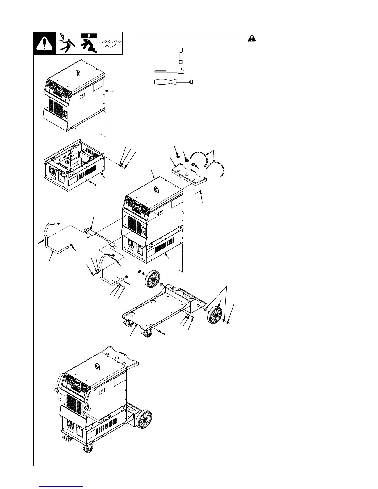
5-12. Installing Optional Handles, Running Gear And Cooler
805 302-A / 805 292-A
! Turn Off welding power source,
disconnect input power.
1 Running Gear 234 359
2 Cooler
3 Wheel 163 463 (2)
4 Flat Washer 602 250 (4)
5 Retaining Ring 121 614 (2)
Install wheels on cylinder tray as shown.
Set cooler on running gear.
. If not installing a cooler, set power
source on running gear.
6 Flat Washer 602 240 (4)
7 Lock Washer 602 211 (4)
8 Screw 601 944 (4)
Secure cooler to running gear using
supplied flat washers, lock washers and
screws.
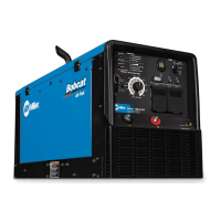
9 Power Source
Set power source on cooler.
Secure power source to cooler using
same hardware that was used to secure
cooler to running gear.
10 Cylinder Support Bracket
11 Bushing 170 647 (2)
12 Bushing 004 214 (1)
13 Screw 128 237 (4)
14 Chain 188 441 (2)
Install cylinder support bracket to rear of
power source and secure with supplied
screws. Install bushings and chains.
15 Handle Bracket
16 Handle (2)
17 Tube Cap (4)
Install tube caps into ends of handles.
Remove 5 screws above louvered panel
on front of power source.
Attach handle bracket to front of power
source using the 5 screws previously
removed.
Remove 2 screws on the side of the cover
on front of power source.
18 Screw 234 483 (2)
Start supplied upper handle mounting
screws into handles by hand on each side
of power source.
19 Screw 604 535 (2)
20 Lock Washer 602 211 (2)
21 Flat Washer 602 240 (2)
Start supplied screws, lock washers and
flat washers into handle bracket by hand
on each side of power source.
22 Screw 604 535 (4)
23 Lock Washer 602 211 (4)
24 Flat Washer 602 240 (4)
Start supplied lower handle mounting
screws, lock washers and flat washers
into handles by hand on each side of
power source.
Tighten all handle hardware.
Tools Needed:
1/2 in.
5/16 in.
2
6
7
8
9
1
2
3
4
15
16
5
6
7
8
13
18
19
20
21
22
23
24
17
10
9
11
12
11
14
 Loading...