OM-253 906 Page 29
input3 2012−05
! Installation must meet all National
and Local Codes − have only qualified
persons make this installation.
! Disconnect and lockout/tagout input
power before connecting input con-
ductors from unit. Follow established
procedures regarding the installation
and removal of lockout/tagout
devices.
! Make input power connections to the
welding power source first.
! Always connect green or green/yel-
low conductor to supply grounding
terminal first, and never to a line ter-
minal.
See rating label on unit and check input volt-
age available at site.
. Right side panel can be removed to allow
attaching primary cable even with
handles installed.
1 Input Power Conductors (Customer
Supplied Cord)
Select size and length of conductors using
Section 5-10. Conductors must comply with
national, state, and local electrical codes. If
applicable, use lugs of proper amperage
capacity and correct hole size.
Welding Power Source Input Power Con-
nections
2 Strain Relief
Route conductors (cord) through strain relief
and tighten screws.
3 Welding Power Source Grounding
Terminal
4 Green Or Green/Yellow Grounding
Conductor
5 Reed Switch (Ground Current Sensor)
(Optional)
Connect green or green/yellow grounding
conductor to welding power source ground-
ing terminal first. If unit is equipped with op-
tional ground current sensor, route grounding
conductor through reed switch two times and
connect to grounding terminal.
6 Welding Power Source Line Terminals
7 Input Conductors L1 (U), L2 (V) And L3
(W)
Connect input conductors L1 (U), L2 (V) and
L3 (W) to welding power source line
terminals.
Reinstall right side panel on welding power
source.
Disconnect Device Input Power Connec-
tions
8 Disconnect Device (switch shown in
OFF position)
9 Disconnect Device (Supply) Grounding
Terminal
10 Disconnect Device Line Terminals
Connect green or green/yellow grounding
conductor to disconnect device grounding
terminal first.
Connect input conductors L1 (U), L2 (V) And
L3 (W) to disconnect device line terminals.
11 Over-Current Protection
Select type and size of over-current protec-
tion using Section 5-10 (fused disconnect
switch shown).
Close and secure door on line disconnect de-
vice. Follow established lockout/tagout pro-
cedures to put unit in service.
5-11. Connecting 3-Phase Input Power (Continued)
Notes
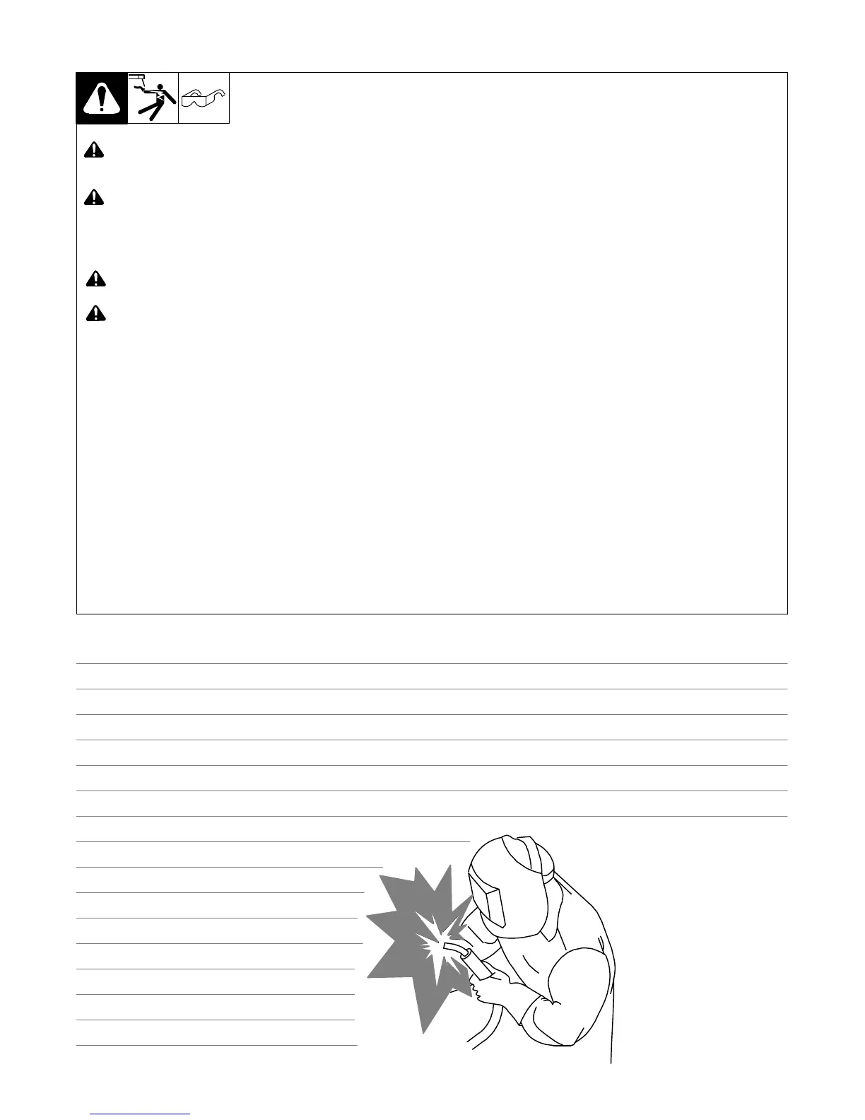
Work like a Pro!
Pros weld and cut
safely. Read the
safety rules at
the beginning
of this manual.
 Loading...