OM-253 906 Page 32
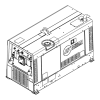
5-14. Proper Ring Terminal Connection To Volt Sense Lead
If volt sense lead is cut or broken at end
with ring terminal, be sure that new ring ter-
minal is connected as shown.
1 Jacket
2 Insulated Tape Or Heat-Shrink
Tubing
3 Center Conductor 10 ga
4 Ring Terminal 1/2 in. Opening
1
Tools Needed:
3
4
2
Ref. 239 780-B
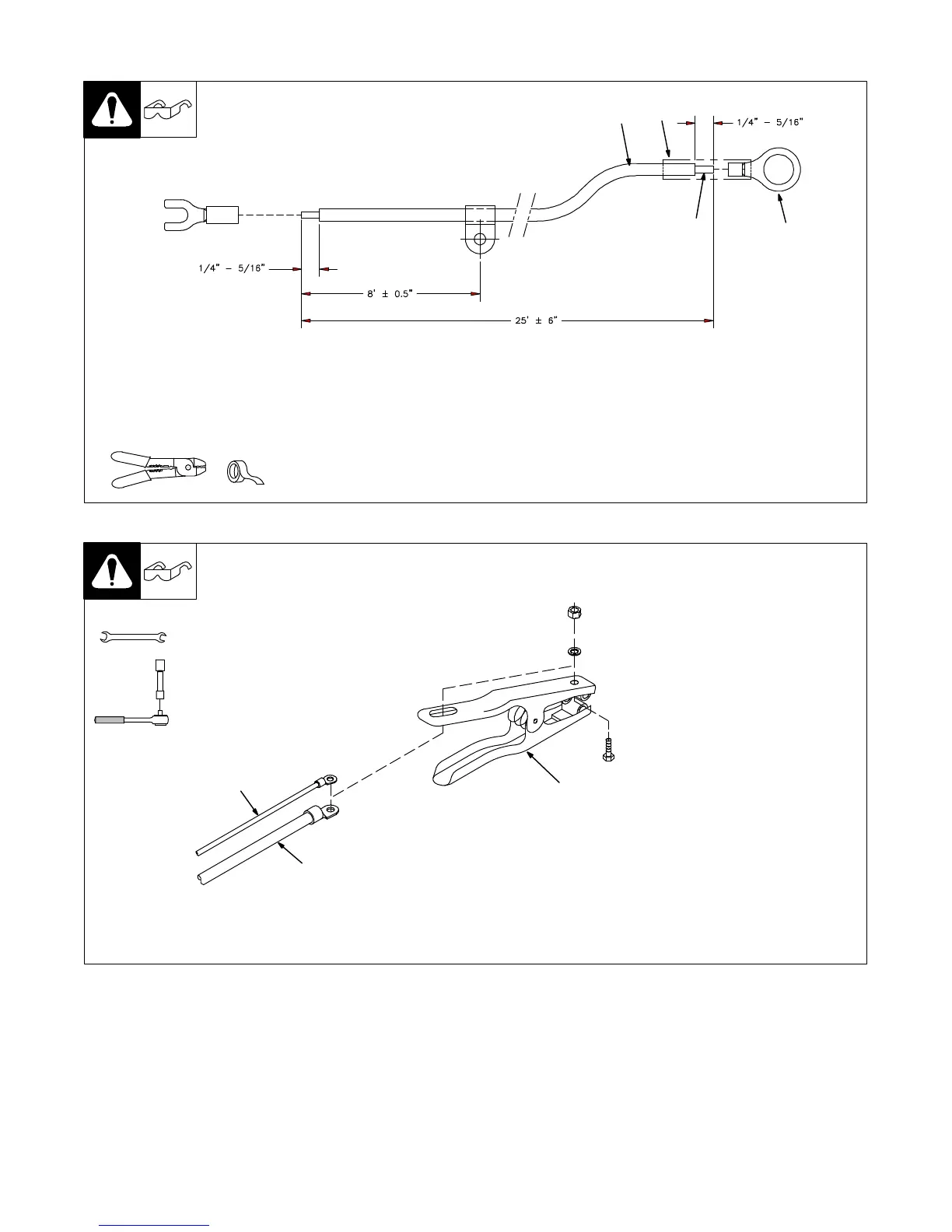
5-15. Connecting Volt Sense Lead And Work Cable To Clamp
805 030-A
Tools Needed:
1/2 in.
3
2
1
1 Volt Sense Lead
2 Work Cable
3 Clamp
. Be sure that volt sense lead
ring terminal is on top of work
cable ring terminal when
connecting to clamp.
Connect volt sense lead and work
cable to clamp.
1/2 in.

 Loading...