EasyManuals Logo

Miller PipeWorx 400 User Manual

Miller PipeWorx 400
116 pages
To Next Page IconTo Next Page
To Previous Page IconTo Previous Page
Page #66 background imageLoading...
Page #66 background image
OM-253 906 Page 60
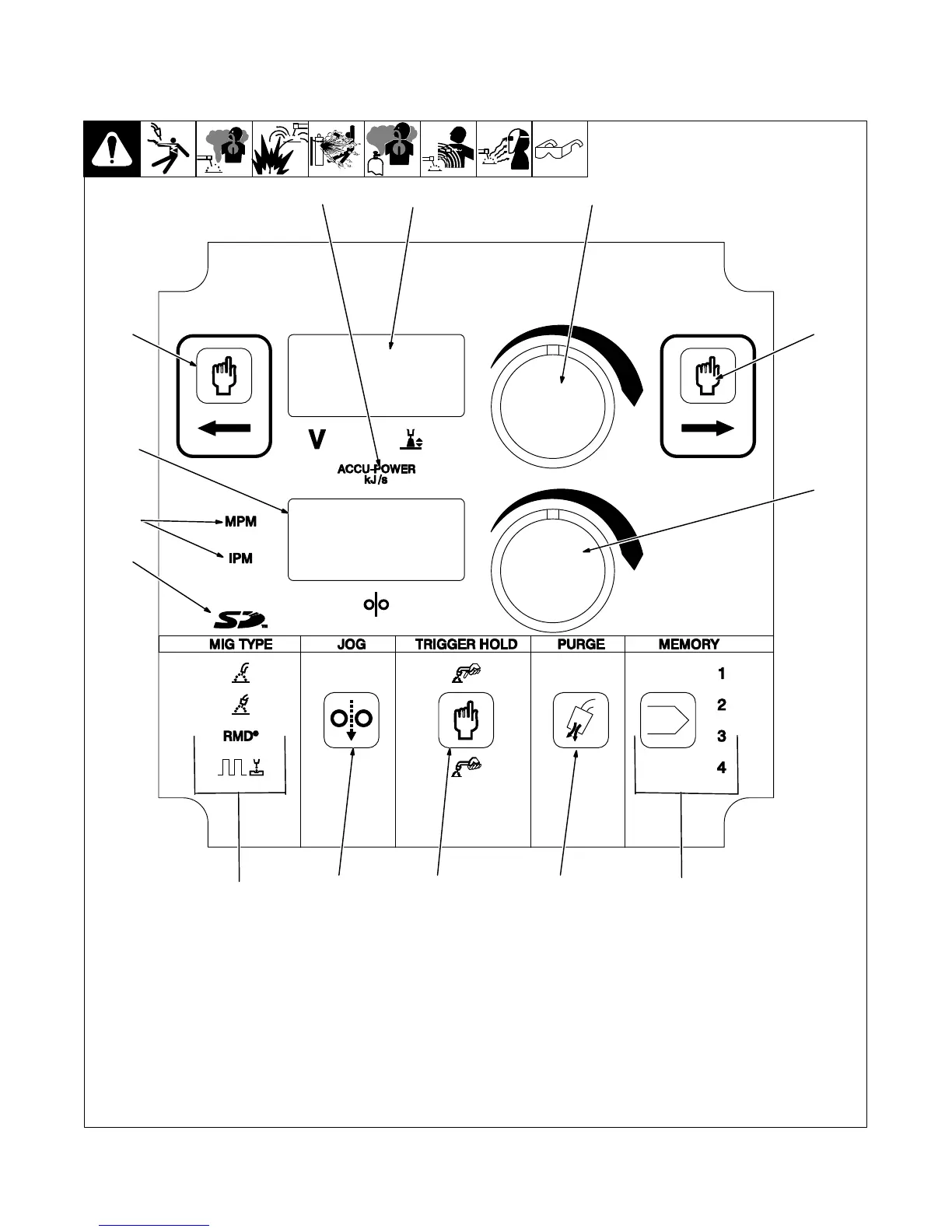
6-9. Wire Feeder Controls
A. Front Panel Controls
. Only illuminated controls can be
changed or adjusted.
1 Left Side Controls Select Button
2 Volts/Arc Length Display
3 Volts/Arc Length Adjust Knob
4 Right Side Controls Select Button*
5 Wire Feed Speed Display
6 Wire Feed Speed Adjust Knob
7 Memory Card Indicator
8 MIG Process Type Indicator
9 Jog Button
10 Trigger Hold Select Button
11 Purge Button
12 Memory Select Button And Location
Indicator
13 Wire Feed Speed Units Indicators
14 Accu-Power Indicator
*Dual Feeder Only
252 620-C
2
5
1
7
13
14
8
12
1110
9
3
6
4

Table of Contents

Questions and Answers:

Question and Answer IconNeed help?

Do you have a question about the Miller PipeWorx 400 and is the answer not in the manual?

Miller PipeWorx 400 Specifications

General IconGeneral
Amperage Range5 - 400 A
Duty Cycle60% at 400 A
ProcessesMIG, Flux-Cored, Stick, DC TIG, Pulsed MIG
Output Voltage Range10 - 44 V
Wire Feed Speed50 - 780 IPM

Related product manuals