EasyManuals Logo

Miller PipeWorx 400 User Manual

Miller PipeWorx 400
116 pages
To Next Page IconTo Next Page
To Previous Page IconTo Previous Page
Page #51 background imageLoading...
Page #51 background image
OM-253 906 Page 45
805 296-A
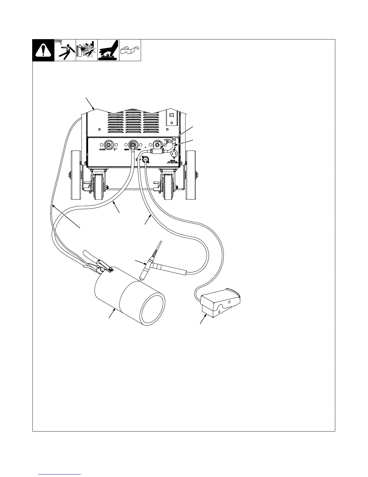
1 Welding Power Source
2 Gas Hose 237 415 (Short Black
Hose Supplied With Power
Source)
3 TIG Block (Customer Supplied)
4 TIG () Weld Cable
5 Work (+) Weld Cable
6 Workpiece
7 TIG Torch
8 Volt Sense Lead
9 Remote Foot Control (Optional)
. Attach volt sense lead to work
clamp and attach work clamp as
close to arc as possible.
5-27. Typical Connection Diagram For One Piece Air-Cooled TIG (GTAW) Torch
(Using Gas Solenoid Inside Power Source)
1
2
3
4
5
6
7
8
9

Table of Contents

Questions and Answers:

Question and Answer IconNeed help?

Do you have a question about the Miller PipeWorx 400 and is the answer not in the manual?

Miller PipeWorx 400 Specifications

General IconGeneral
Amperage Range5 - 400 A
Duty Cycle60% at 400 A
ProcessesMIG, Flux-Cored, Stick, DC TIG, Pulsed MIG
Output Voltage Range10 - 44 V
Wire Feed Speed50 - 780 IPM

Related product manuals