EasyManuals Logo

Miller PipeWorx 400 User Manual

Miller PipeWorx 400
116 pages
To Next Page IconTo Next Page
To Previous Page IconTo Previous Page
Page #79 background imageLoading...
Page #79 background image
OM-253 906 Page 73
SECTION 7 MAINTENANCE AND TROUBLESHOOTING
! Disconnect power before maintaining.
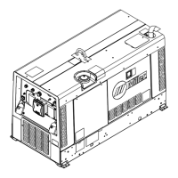
7-1. Routine Maintenance
n = Check ~ = Clean l = Replace
Every
3
Months
l Unreadable Labels ~ Weld Terminals nl Weld Cable l Cracked Parts
n 14-Pin Cord n Gas Hose and Fittings n Gun Cable
l Cracked Electrode
Holder Parts
l Cracked Torch Body
Every
6
Months
Or
~ Inside Unit ~ Drive Rolls
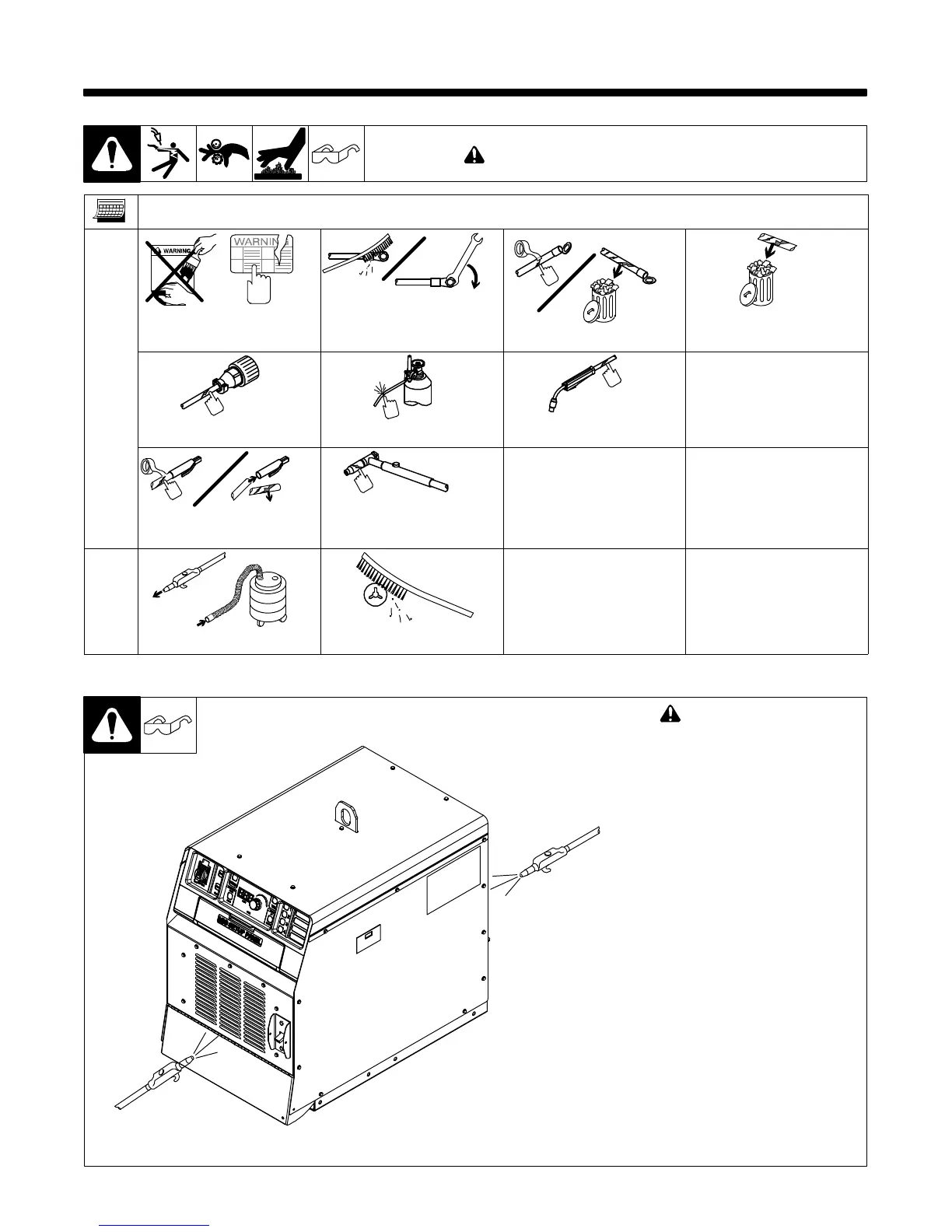
7-2. Blowing Out Inside of Unit
! Do not remove case when
blowing out inside of unit.
To blow out unit, direct airflow
through front and back louvers as
shown.
Ref. 805 142-A

Table of Contents

Questions and Answers:

Question and Answer IconNeed help?

Do you have a question about the Miller PipeWorx 400 and is the answer not in the manual?

Miller PipeWorx 400 Specifications

General IconGeneral
Amperage Range5 - 400 A
Duty Cycle60% at 400 A
ProcessesMIG, Flux-Cored, Stick, DC TIG, Pulsed MIG
Output Voltage Range10 - 44 V
Wire Feed Speed50 - 780 IPM

Related product manuals