OM-253 906 Page 37
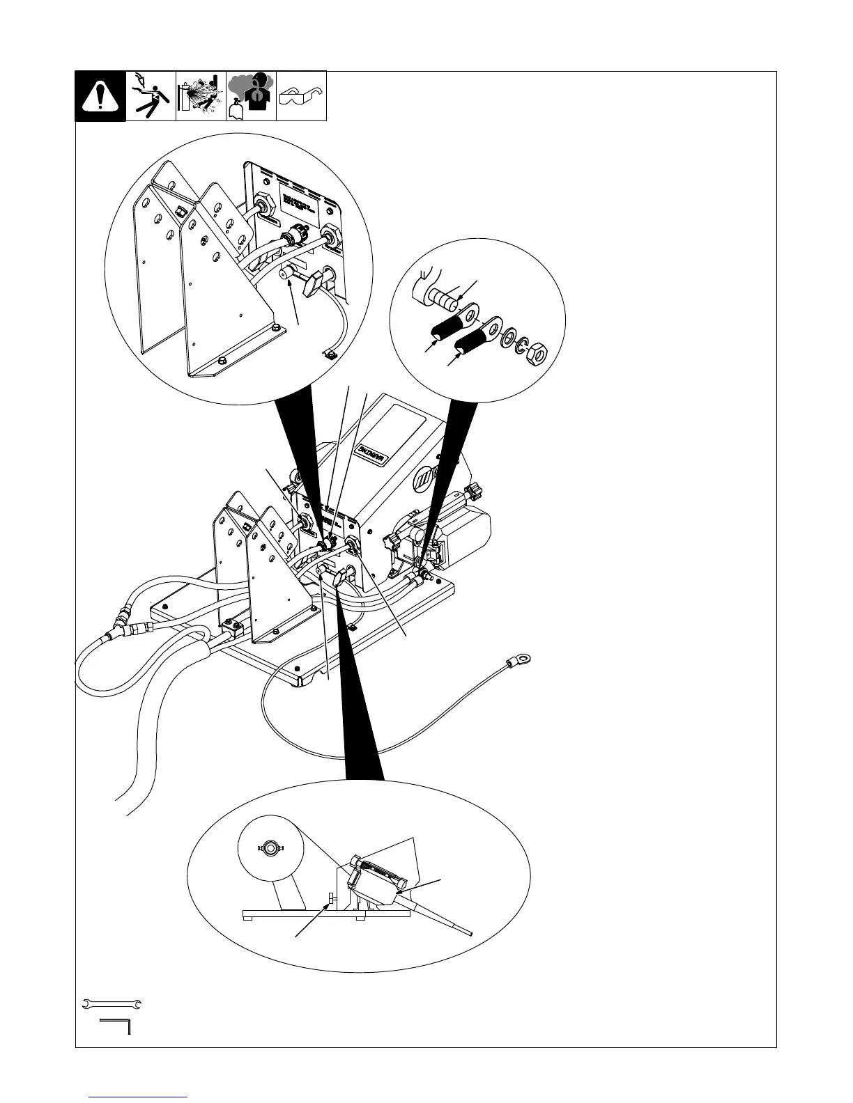
5-20. Wire Feeder Rear Panel Connections And Rotating Drive Assembly
805 155-A / Ref. 804 766-A / 802 825-A
1 14-Pin Control Cable
2 Shielding Gas Valve Fittings
Requires fitting with 5/8-18
right-hand threads. Connect
customer-supplied gas hose.
3 Weld Cable Terminal
4 Jumper Weld Cable From
Right Side Drive Assembly
(Dual Model Only)
5 Weld Cable
6 Drive Assembly
7 Drive Assembly Rotation
Knob
To rotate the drive assembly,
loosen drive assembly rotation
knob, rotate drive assembly, and
tighten knob.
8 Rating Label Location
9 Volt Sense Terminal
9/16, 5/8 in.
Tools Needed:
3/16 in.
6
7
3
9
4
5
2
1
8
2
9

 Loading...