OM-253 906 Page 49
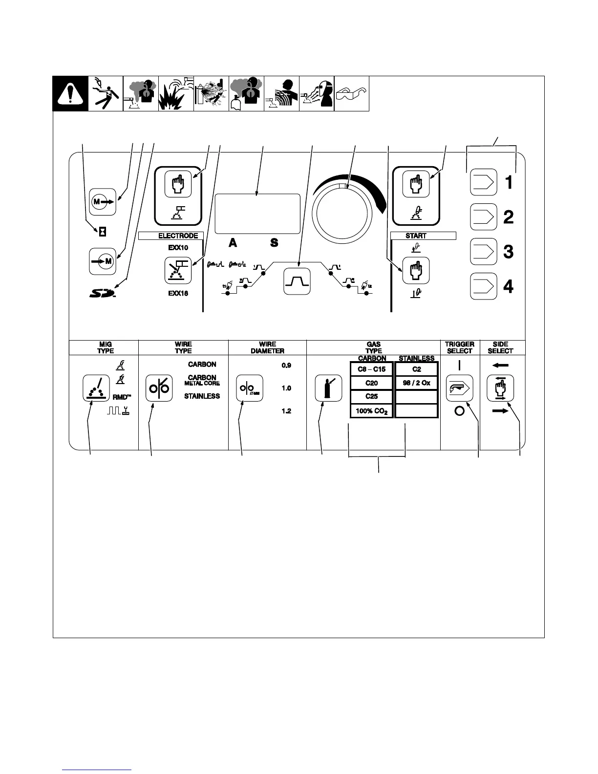
6-2. Welding Power Source Controls
A. Front Panel Controls
. Only illuminated controls can be
changed or adjusted.
1 Memory Card Busy Indicator
2 Memory Card Save Button
3 Memory Card Load Button
4 Memory Card Indicator
5 Memory Location Buttons 1-4
6 Stick Process Select Button
7 Stick Electrode Type Select Button
8 Ammeter Display
9 Amperage Adjust Knob
10 TIG Process Select Button
11 TIG Starting Method Select Button
12 MIG Process Type Select Button
13 Wire Type Select Button
14 Wire Diameter Select Button
15 Gas Type Select Button
16 Gas Selection Table
17 Trigger Select Button
18 Side Select Button
19 TIG Sequence Controls
252 613-B
12
11 10
9
8
76
4
3
1
2
5
17
19
18
16
15
14
13
 Loading...