OM-253 906 Page 34
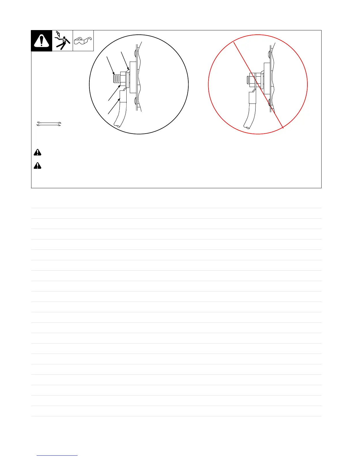
5-17. Connecting Weld Output Cables
803 778-B
! Turn off power before connecting to
weld output terminals.
! Failure to properly connect weld
cables may cause excessive heat
and start a fire, or damage your
machine.
1 Weld Output Terminal
2 Supplied Weld Output Terminal Nut
3 Weld Cable Terminal
4 Copper Bar
Remove supplied nut from weld output
terminal. Slide weld cable terminal onto
weld output terminal and secure with nut so
that weld cable terminal is tight against
copper bar. Do not place anything
between weld cable terminal and copper
bar. Make sure that the surfaces of the
weld cable terminal and copper bar are
clean.
Tools Needed:
19 mm (3/4 in.)
4
2
3
Do not place
anything between
Incorrect Installation
1
weld cable terminal
and copper bar.
Notes
 Loading...