OM-253 906 Page 35
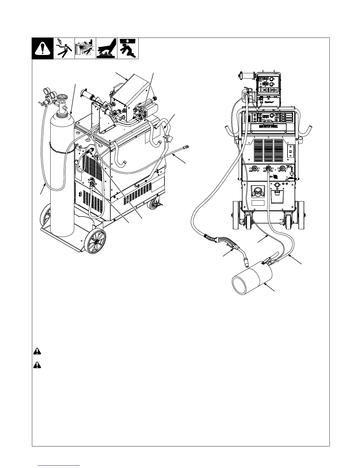
5-18. Typical Connection Diagram For MIG (GMAW) Equipment With Feeder
On Power Source
! Do not put feeder where welding
wire hits cylinder.
! Do not move or operate equipment
when it could tip.
1 Welding Power Source
2 Wire Feeder
3 MIG Connection
4 Positive (+) Weld Cable
5 Feeder Control Cable Connection
6 Gas Hose
7 Gas Cylinder
Connect 14-pin plug to rear of power
source, and connect 14-socket plug to rear
of wire feeder. Connect one end of weld
cable to weld terminal on rear of power
source. Connect remaining end of weld
cable to wire feeder drive housing. Connect
one end of gas hose to regulator/flowmeter
on gas cylinder and connect remaining end
of gas hose to gas solenoid connector on
rear of feeder or Y-hose for dual wire feeder.
8 Work (−) Weld Cable
. Attach volt sense lead to work clamp
and attach work clamp as close to arc
as possible.
9 Volt Sense Cable
10 Workpiece
11 Welding Gun
254 079-A
1
6
4
7
2
5
3
9
8
11
9
10
 Loading...