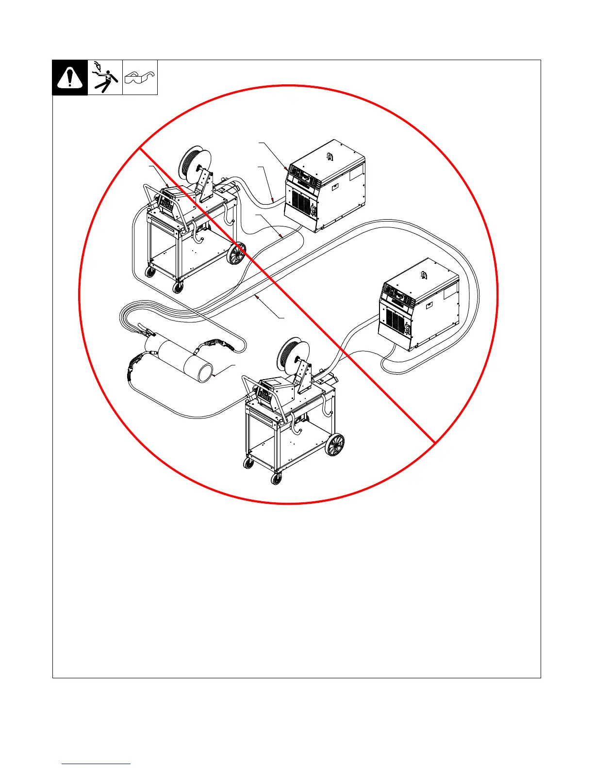
EasyManuals Logo

Miller PipeWorx 400 User Manual

Miller PipeWorx 400
116 pages
To Next Page IconTo Next Page
To Previous Page IconTo Previous Page
Page #47 background imageLoading...
Page #47 background image
OM-253 906 Page 41
B. Bad Setup
805 290-B
1 Welding Power Source
2 Composite Cable
3 Work Cable
4 Voltage Sensing Lead
5 Wire Feeder
6 Workpiece
This arrangement is a bad setup due to
sensing leads being directly in the current
flow path of the welding arc. Interaction
between welding circuits will affect voltage
drop in the workpiece. The voltage drop
across the workpiece will not be measured
correctly for the voltage feedback signal.
Voltage feedback to the welding power
sources will not be correct at either sense
lead and result in poor arc starts and arc
quality.
1
2
3
4
5
6

Table of Contents

Questions and Answers:

Question and Answer IconNeed help?

Do you have a question about the Miller PipeWorx 400 and is the answer not in the manual?

Miller PipeWorx 400 Specifications

General IconGeneral
Amperage Range5 - 400 A
Duty Cycle60% at 400 A
ProcessesMIG, Flux-Cored, Stick, DC TIG, Pulsed MIG
Output Voltage Range10 - 44 V
Wire Feed Speed50 - 780 IPM

Related product manuals