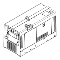
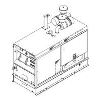
OM-253 906 Page 91
Description
Part
No.
Dia.
Mkgs.
Item
No.
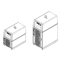
Figure 9-1. Main Assembly
Quantity
1 +250832 Panel, Rear 1... ......... .. ........................................................
2 CB2 093995 Supplementary Pro, Man Reset 1P 15A 250VAC Frict 1... ... .. .. ...................
3 PC11 244471 Circuit Card Assy, PS/Feeder Interface 1... .. . .. ................................
4 228036 Valve, 24VAC 1way .750−14 Thd 2.0mm Orf 100 PSI 1... .......... .. ....................
5 236638 Hose, Nprn Brd No 1 x .187 ID x 40.000 1... .......... .. ...............................
6 010467 Conn, Clamp Cable 1.250 1... .......... .. ............................................
7 220805 Nut, 750−14 NPS 1.48Hex .41h Nyl 1... .......... .. ...................................
8 181181 Label, Warning Match Input Power To Voltage 1... ........... .. ..........................
237163 Label, MIG Output 1................ .. ..................................................
237157 Label, CB2 1................ .. .........................................................
238560 Label, TIG Gas In 1................ .. ...................................................
254053 Label, To Wirefeeder 1................ .. ................................................
9 C3, C4,... .
C5, C6 192935 Capacitor, Elctlt 2700 uf 450 VDC Can 2.52 Dia 4.. .........................
218004 Label, Warning Electric Shock/Exploding Parts 3................ .. ..........................
217040 Nut, Nylon M12 Thread Capacitor Mounting 4................ .. ............................
10 PC4 231559 Circuit Card Assy, Interconnecting 1... ... .. .. .....................................
11 185214 Bus Bar, Interconnecting 1... .......... .. .............................................
12 +240841 Panel, Side RH 1... ......... .. .....................................................
13 237155 Label, Important Input Power/Relink Connections 1... .......... .. .......................
14 234271 Sheet, Insulator Side Panel 1... .......... .. ..........................................
15 FM1, FM2 222728 Fan, Muffin 24VDC 3000 RPM 255 CFM 2... .. ...............................
16 233501 Bracket, Fan 1... .......... .. .......................................................
17 L1 180026 Inductor, Input 1... ... .. .. ......................................................
Windtunnel, RH w/Cmpnts (Includes) 1........................... ..................................
18 030170 Bushing, Snap−In Nyl .750 ID x 1.000 Mtg Hole 2... .......... .... .......................
19 025248 Stand−Off, Insul .250−20 x 1.250 Lg x .437 Thd 4... .......... .... .......................
20 W1 180270 Contactor, Def Prp 40A 3P 24VAC Coil w/Boxlug 1... ... .. .... ......................
21 CT1 233620 Xfmr, Current 500 Turn Polarized 1... ... .. .... ....................................
22 177547 Bushing, Snap−In Nyl Ct−Mount 1.125 Mtg Hole 1... .......... .... .......................
23 010493 Bushing, Snap−In Nyl .625 ID x .875 Mtg Hole 4... .......... .... ........................
24 233462 Windtunnel, RH 1... .......... .... ...................................................
25 PM1, PM2 240144 Kit, Transistor IGBT Module 1... .... ........................................
26 179930 Heat Sink, Power Module 1... .......... .... ..........................................
27 RT1 173632 Thermistor, Ntc 30k ohm @ 25 Deg C 12.00 in Lead 1... ... .. .... ...................
28 SR1 249052 Kit, Rectifier, Integ Bridge 1... ... .. .... ..........................................
29 C1, C2 230273 Capacitor, Polyp Film .5 uf 1000 VRMS +/−10% 2... .. .. .........................
30 L2 233438 Inductor, Output 1... ... .. .. ....................................................
31 L3, L4 233617 Inductor, DI−DT 2... .. . .. .....................................................
32 218566 Gasket, Inductor Mounting E70 Ferrite Core 2... .......... .. ............................
33 CB1 083432 Supplementary Pro, Man Reset 1P 10A 250VAC Frict 1... ... .. .. ...................
34 RC2 134837 Rcpt, Str Grd 2P3W 15A 125V Single *5−15R 1... ... .. .. ..........................
35 170647 Bushing, Snap−In Nyl 1.312 ID x 1.500 Mtg Hole 2... .......... .. ........................
36 HD1 168829 Transducer, Current 1000A Module 1... ... .. .. ....................................
37 234358 Base, w/ Pem Nuts 1... .......... .. ..................................................
38 229325 Foot, Mtg Unit 4... .......... .. ......................................................
+When ordering a component originally displaying a precautionary label, the label should also be ordered.
To maintain the factory original performance of your equipment, use only Manufacturer’s Suggested
Replacement Parts. Model and serial number required when ordering parts from your local distributor.
 Loading...
