30
Pellerin Milnor Corporation
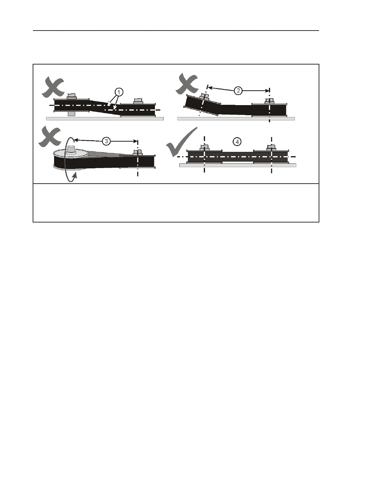
Figure 9. Pulley and Shaft Position
Views of Incorrect and Correct Positions
Legend
1. Not aligned: Pulley grooves are in different planes.
2. Not aligned: Pulley grooves are in different planes and shafts are not parallel.
3. Not aligned: Pulley shafts are not parallel (not at the same slope).
4. Aligned: Pulley grooves are in the same plane and shafts are parallel.
Keep Run-Out in Tolerance
BNUUUM02.C05 0000274606 A.4 A.2 2/4/20 8:08 AM Released
Axial run-out The difference between the minimum and maximum distance between the face
of a pulley and a plane perpendicular to the pulley shaft (Figure 10 , item 1). Incorrect instal-
lation or damage can cause a pulley to be not at a 90 degree angle to the shaft.
Radial run-out The difference between the minimum and maximum diameter in one turn (Fig-
ure 10 , item 2). If a force causes damage to a pulley, it can bend. It will not have a circular
shape.
Drive Assemblies