50
Pellerin Milnor Corporation
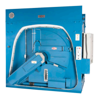
• When the cylinder turns, air pressure at Figure 24: A Typical First and Second Brake on a
Divided Cylinder Machine, page 49 , item 1 compresses the spring and releases the brake.
• When you operate the stop control, air pressure at 1 is removed. Then the spring in the air cyl-
inder applies the brake.
• If you open the door, the 2nd brake is applied. Then the air pressure at Figure 24: A Typical
First and Second Brake on a Divided Cylinder Machine, page 49 , item 2 and the spring apply
the brake.
The Second Brake
BNWUUM03.T11 0000279000 A.4 A.7 A.2 3/17/20 11:57 AM Released
If your machine has a second brake which uses air pressure and spring pressure, it will have a
pressure regulator. Make sure that you adjust the air pressure of the second brake (Figure 24: A
Typical First and Second Brake on a Divided Cylinder Machine, page 49 , item 2) to 10 – 12 PSI
(0.7-0.84 kg/cm-cm).
Drive Assemblies