90
Pellerin Milnor Corporation
Use “Antiseize” lubricant on all threads.
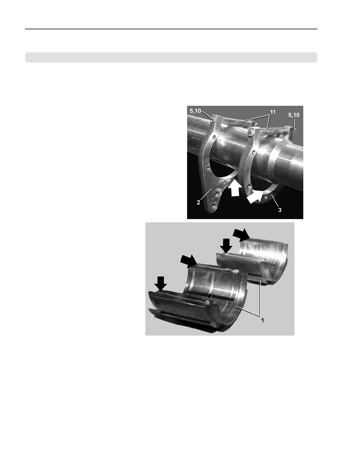
Refer to the illustrations next to each step. Item numbers shown refer to the parts list.
1. Slide the front and rear flanges (Items 2 & 3) on-
to the shaft. Bore chamfers (large arrows) must
face inward. Assemble spacers (Item 11) and en-
sure bolts are loose. (Only for new installation
and complete replacement.)
2. Apply a thin bead of high temper-
ature RTV silicone to the bronze
bushing (Item 1) seams. Large ar-
rows show surfaces on which to
apply silicon.
Assembly Procedure
5 Sheets
6044SR2, 72044SR2/SR3
BPWG6B02 / 2020174
BPWG6B02.1 0000288467 A.4 A.9 4/22/20 4:56 PM Released
Drive Assemblies