Pellerin Milnor Corporation 13
therein caused in this way. Much more information on this subject is provided in Section 1.4 :
Prevent Damage from Chemical Supplies and Chemical Systems, page 7 . Consult this document
before connecting a pumped chemical system.
1.5.4 Connecting Devices to Receive Injection Signals
BNCJVI01.R04 0000181445 A.4 A.5 B.3 1/2/20 1:16 PM Released
For 36-inch and 42-inch V_J models, injection signals provide either 110VAC/50Hz or 120VAC/
60Hz potential. For 30-inch V_J and all F_J/F_B, H_J, and X_J models, injection signals provide
either 220VAC/50Hz or 240VAC/60Hz potential. Each signal can accomodate one apparatus not
exceeding 37 milliamperes. Inject signals cannot be made potential-free.
CAUTION: Avoid Component Damage — Board components will burn out and re-
quire board replacement if devices driven by inject signals do not meet the
electrical specifications. Pumps generally draw a higher current and will
burn out board components.
1.5.5 Connecting Chemicals to 30-inch T5_ Models
BNCJUI01.C03 0000210891 A.4 A.5 1/2/20 1:16 PM Released
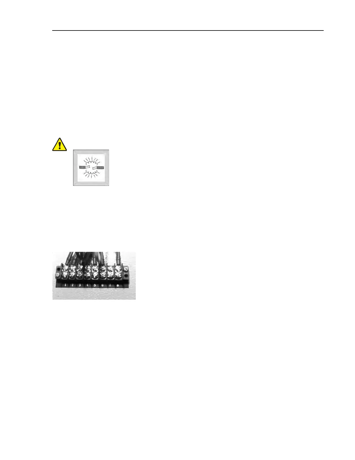
Acquire signals at terminal strip TBS in the incoming power box (Figure 6 ). Pins 1 through 5 are
for chemicals 1 through 5 respectively, and pin 8 is common. The specified voltage is enabled be-
tween the appropriate pin and common whenever an injection is commanded.
Figure 6. Terminal Strip TBS in T-style Machine
Commissioning
 Loading...