72
Pellerin Milnor Corporation
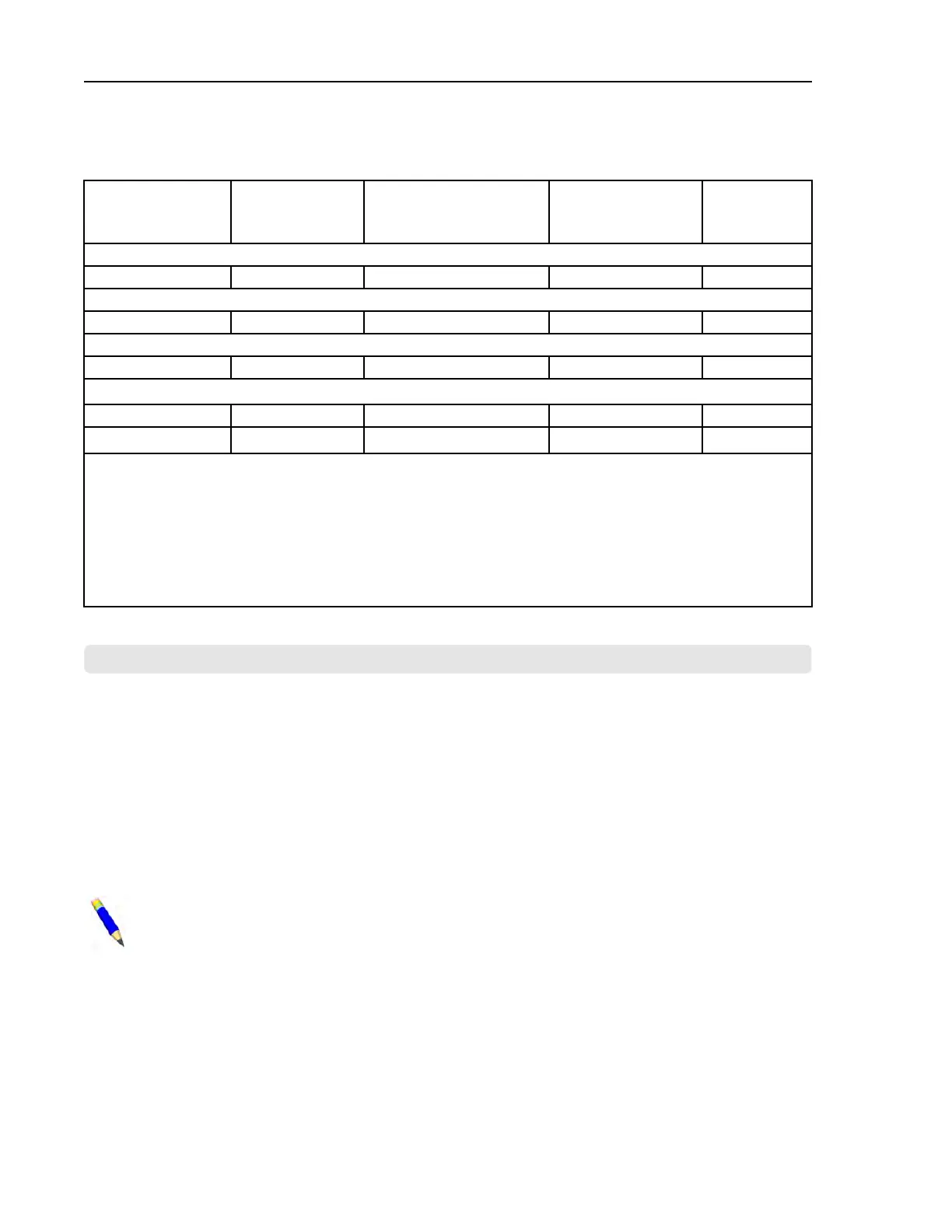
Table 22. DIP Switch Positions for E-P Plus
®
and E-P Express
®
Machines (External transmit
button required)
Processor Board
Part Number
Processor
Board Revision
Code
Machine Software
and Revision
Storage Device
Software and
Revision
DIP Switch
Setting
30015HxJ and 30022HxJ Models
08BH18EPDT
K
WUH7JA/2200E WUNTIA/00008
E
VxJ Models
08BH18EPDT
K
WUV7J1B/2200K WUNTIA/00008
E
30015T5X and 30022T5X Models
08BH18EPYT
K
WUEPXPRSA/22004 WUNTIA/00008
E
All E-P Express Gear Guardian Models
08BH18EPYT
K
WUT5XGGA/22GGF WUNTIA/00008
E
08BH18EPWT
K
WUMWRXGG/(any) WUNTIA/00008
E
Key:
A
All switch positions OFF
B
Position 4 ON; all others OFF
C
Position 5 ON; all others OFF
D
Positions 1 and 5 ON; all others OFF
E
Positions 4 and 5 ON; all others OFF
BNCUUP02 / 2018303
BNCUUP02 0000196987 A.9 1/2/20 1:30 PM Released
5.3 Construction of External Serial Link Cables
BNCUUP02.C01 0000196986 A.4 A.9 1/2/20 1:30 PM Released
This document provides information for on-site fabrication of certain types of serial communica-
tion cables. Programmable data can be transferred between compatible machines or between a
machine and a Milnor
®
serial memory storage device (see related note below), using the down-
load cables described in Section 5.3.2.2 : Connecting Two or More Machines for Machine-to-ma-
chine Transfer, page 74 and Section 5.3.2.3 : Connecting a Machine to a Serial Memory Storage
Device, page 75 respectively. These cable(s) connect to the cabinet-mounted 9-pin DIN type re-
ceptacle shown in Figure 14: 9-Pin DIN Connector Pin Identification (from wire entry side of
connectors), page 73 and may be installed temporarily or permanently, as appropriate.
NOTE: The currently approved printers and printer configuration settings are provided
in Section 5.4 : Printer Requirements and Settings, page 76 . A pre-assembled machine-
to-printer cable similar to the cable described here, is available from Milnor (P/N
10YMK2PNTR).
Supplemental Information
 Loading...