Pellerin Milnor Corporation 75
simultaneously. This cable is referred to as a daisy chain because it runs in segments from ma-
chine to machine, connecting all machines in the group.
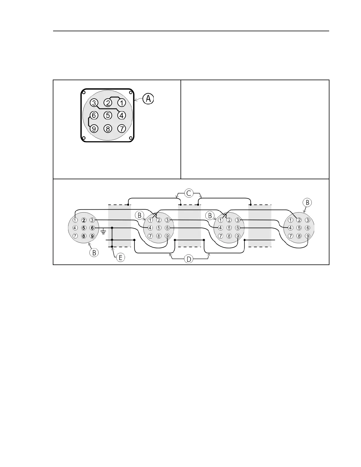
Figure 15. Wiring Diagram for Cable to Connect Two or More Machines
Receptacle On Each Machine
Legend
A...Receptacle on machine (with male pins). Pin functions
are as follows: 1&2=Serial low; 3&4=Serial high;
6&9=Ground; 5&7=Not used in this application; 8=
Not used in this application. See previous, related cau-
tion statement.
B...Plug on cable (with female pin sockets)
C...Connect together each segment of shield so that it has
continuity across entire daisy chain.
D...Connect together each segment of an unused conduc-
tor so that it has continuity across entire daisy chain.
E...Tie shield and spare conductor(s) on one end of daisy
chain to ground. Leave unconnected on other end of
daisy chain.
Cable Wiring
The internal connections on each receptacle (machine) between pins 1 and 2, 3 and 4, and 6 and 9
make it easier to wire the cable because it is not necessary to jumper these pins together on the ca-
ble. However, this also means that every plug on the daisy chain must be plugged into a recep-
tacle. Otherwise, the serial low, serial high, and ground conductors will not have continuity
across the entire daisy chain and some machines will not receive data.
Rules and details about downloading among machines are fully described in the programming
section of the reference manual.
5.3.2.3 Connecting a Machine to a Serial Memory Storage Device
BNCUUP02.C06 0000197240 A.4 A.9 1/2/20 1:30 PM Released
The cable used with the serial memory storage device (download box) available from Milnor, see
related note in Section 5.3 : Construction of External Serial Link Cables, page 72 , is permanently
attached to the storage device. Cable fabrication, as shown in Figure 16: Wiring Diagram for Ca-
ble to Connect a Machine to a Serial Memory Storage Device, page 76 , is not required except for
replacing a damaged cable. The memory storage device is the only application in which the
power conductor (Pin 8) is used.
Supplemental Information
 Loading...