iv
Pellerin Milnor Corporation
5.3.2.3 Connecting a Machine to a Serial Memory Storage Device ......................75
5.4 Printer Requirements and Settings ..................................................................................76
5.4.1 Cable Requirements...............................................................................................76
5.4.2 Configuring the Citizen GSX-190 Printer.............................................................77
5.4.3 Configuring the Epson LX300 Printer ..................................................................77
5.4.4 Previous Printer Models ........................................................................................78
Figures
Figure 1 How Rotating Forces Act On the Foundation ............................................................6
Figure 2 Incorrect Configurations That Let the Chemical Supply Go In the Ma-
chine by a Siphon........................................................................................................8
Figure 3 Incorrect Configurations That Let the Chemical Supply Go In the Ma-
chine by Gravity..........................................................................................................9
Figure 4 Examples of Manifolds for Chemical Tubes. Your equipment can look
different.......................................................................................................................9
Figure 5 A Configuration that Prevents Flow in the Machine When the Pump is
Off (if the chemical tube and tank have no pressure) ...............................................10
Figure 6 Terminal Strip TBS in T-style Machine....................................................................13
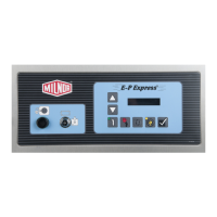
Figure 7 E-P Express
®
Control Panel......................................................................................14
Figure 8 Location of DIP Switches .......................................................................................18
Figure 9 Controls Identification on Serial Memory Storage Device ......................................38
Figure 10 Worksheet .................................................................................................................47
Figure 11 Processor Board ........................................................................................................64
Figure 12 Serial Memory Storage Device.................................................................................71
Figure 13 Rear View of Circuit Board ......................................................................................71
Figure 14 9-Pin DIN Connector Pin Identification (from wire entry side of
connectors)................................................................................................................73
Figure 15 Wiring Diagram for Cable to Connect Two or More Machines ...............................75
Figure 16 Wiring Diagram for Cable to Connect a Machine to a Serial Memory
Storage Device..........................................................................................................76
Tables
Table 1 Trademarks ................................................................................................................2
Table 2 How to Read and Change Data ..................................................................................4
Table 3 DIP Switch Settings for Industry Configurations ....................................................19
Table 4 Codes for Inject Times of 100 Seconds and Longer ................................................26
Table 5 Summary of Drain Type Choices .............................................................................28
Table 6 Controllers Capable of Transferring Memory .........................................................36
Table 7 Sample Formula .......................................................................................................44
Table 8 Codes for Inject Times of 100 Seconds and Longer ................................................45
Table 9 Formula 01 - Light Soil Turnouts ............................................................................48
Table 10 Formula 02 - Heavy Soil Turnouts ..........................................................................48
Table 11 Formula 03 - Light Soil Moisture Barriers ..............................................................48
Table 12 Formula 04 - Heavy Soil Moisture Barriers ............................................................49
Table 13 Formula 05 - Oil-contaminated Gear .......................................................................49
Table 14 Formula 06 - Brush Gear .........................................................................................49
Contents

 Loading...