A5/A3™ Service Manual 046-001141-00 5 - 53
Repair and Troubleshooting Pneumatic Circuit System Problems
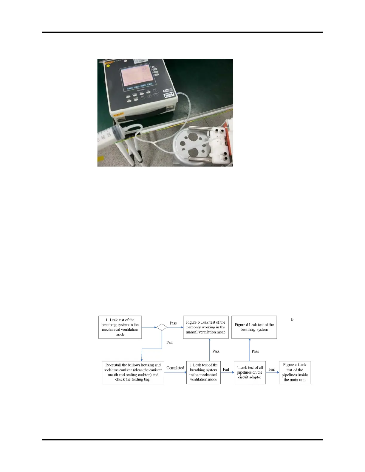
FIGURE 5-54
9. Push in the push rod of the injector to let the pressure reading on the anesthesia machine
calibration device rise to 70 to 90 cmH2O and then stop pushing. Keep the relative position
between the push rod and the injector unchanged. If the pressure reading on the anesthesia
machine calibration device does not fall more than 5cmH2O within 15s, this test is passed.
If test “A” is failed and “B” passed, it indicates that the flow sensor pressure sampling pipeline on the
breathing system is damaged. In this case, replace the breathing system. If both tests “A” and “B” are
failed, check the sampling lines and connectors inside the main unit, seals and solenoid valve of the
circuit adapter assembly until test “B” is passed. Then perform test “A”. If test “A” is still failed, it
indicates the flow sensor pressure sampling pipeline on the breathing system is damaged. In this
case, replace the breathing system.
5.3.4.2 Leak Test of Low-pressure Pneumatic Circuit System
After making sure that the flow sensor pressure sampling pipeline is not leaky, perform leak tests of
the low-pressure pneumatic circuit system as shown in the following figures.
FIGURE 5-55 System Leak Test