EasyManuals Logo

Mindray A5 Service Manual

Mindray A5
436 pages
To Next Page IconTo Next Page
To Previous Page IconTo Previous Page
Page #95 background imageLoading...
Page #95 background image
A5/A3â„¢ Service Manual 046-001141-00 2 - 9
Installation Guide Assembly
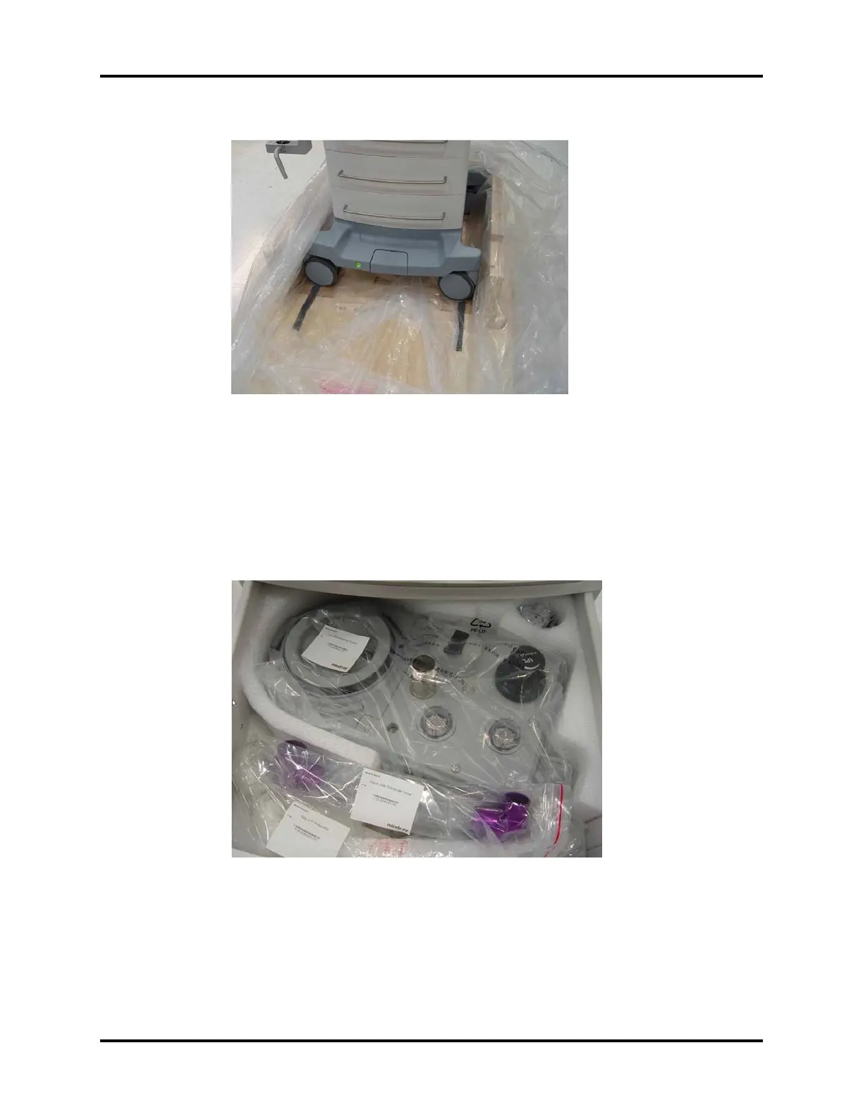
FIGURE 2-12
NOTE: Check that there are green beads in the desiccant pack and that they
have not turned pink.
14. Rotate the casters 90° and carefully roll the A5/A3 unit down the ramp. Remove the bag from
the unit. Save the bag in case repacking is needed.
15. Open the bottom drawer and remove the Breathing Assembly (P/N: 115-017020-00 ) and the
Bag Arm Assembly (P/N: 115-017021-00 ).
FIGURE 2-13
16. Install the Breathing Assembly on the side of the A5/A3. Align the Assembly carefully, and then
push it firmly towards the A5/A3 until the Assembly clicks into place.

Table of Contents

Other manuals for Mindray A5

Questions and Answers:

Question and Answer IconNeed help?

Do you have a question about the Mindray A5 and is the answer not in the manual?

Mindray A5 Specifications

General IconGeneral
TypeAnesthesia Machine
BrandMindray
ModelA5
Power Supply100-240 V AC, 50/60 Hz
Ventilation ModesSIMV, PSV
FlowmetersO2, N2O, Air
Vaporizer CapacityUp to 3 vaporizers
Safety FeaturesO2 failure protection, low pressure alarm
Gas ModuleOptional integrated gas module
Integrated Air CompressorOptional
Patient MonitoringIntegrated monitoring with optional modules

Related product manuals