Structure and Assembly/Disassembly 9-31
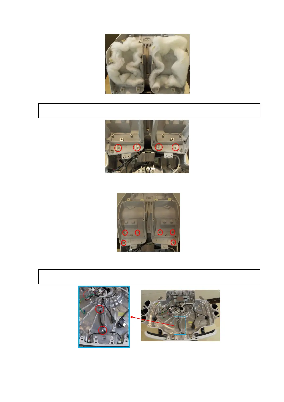
5. Unscrew 4 M4 X 12 cross panhead screws with screwdriver (M3, M4) to remove 4 clips.
Be aware of the orientation of the clip. Align the locating pin of the clip with the locating
hole of the control panel base when performing the installation.
6. Unscrew 6 M5 X 16 round inner head screw (with the pad) by M5 spanner to remove the base
of the side control panel upwards.
7. Unscrew 2 M4 X 12 cross panhead screws on UC-0.5 lock knob with screwdriver (M3, M4) to
remove the wires.
The orientation and the position of the fixing clip should keep same with these in the
following figure.

 Loading...


