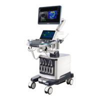
2-2 Specifications
No. Name Function
Connected to ECG leads and USB drive, etc.
<7> Probe port Sockets connecting transducers and the main unit.
Used for moving the system.
<9> Central brake
Used for securing the system or moving the system straight
forward.
Step on the left brake pedal to lock the device from being
moved.
Step on the right walking pedal to move the device straight.
<10>
Intracavitary probe
holder
Used for placing the probe.
<11>
Rotatable knob on the
control panel
Lock or unlock the movement of the control panel
<12>
Ascending/descending
button
The button to ascending or descending the system.
<13> Control panel
Key- pressing operator-system interface or accessible to
control
<14> Transducer (gel) holder Used for placing transducers and gel temporarily.
<15> Monitor support arm
Supports the monitor, for adjusting the angle of LCD
monitor.
<16>
The control panel
stretch mechanism
Used for stretching or rotating the control panel.
Note: subject to the Control Panel Moving Mechanism
Assembly when the user purchases the product.
<17>
mechanical assembly
Used for adjusting the height of the control panel
<18>
The back handle of
main unit
Used for winding the cables up and assisting for moving the
system.
<19> I/O Panel Port panel for input and output signals.
<20>
Power supply assembly
for the system
Provides the power to the system.

 Loading...