4. Device installation | 4.2 - Mechanical preparation | 32
– Establish a low-resistance connection between the screen clamping rail
and the cabinet/housing.
– Use a metallic or metalized connector housing.
– Establish equipotential bonding between devices/system components
(this is essential for Ex applications).
– Use a standardized reference potential.
– Connect the mounting rail to protective ground.
– Keep measurement and data cables away from power cables.
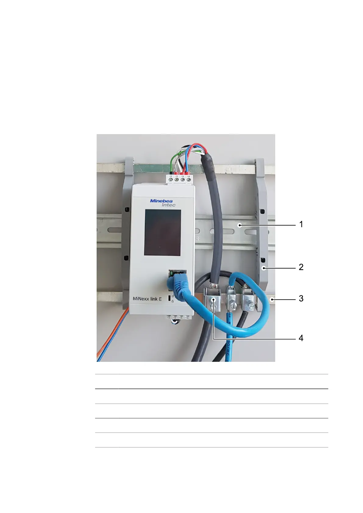
Pos. Name
1 Mounting rail (35mm)
2 Rail connector (e.g. Phoenix AB-SK 65D)
3 Screen clamping rail (e.g. Phoenix NLS-CU 3/10)
4 Screen clamp (e.g. Phoenix SK8-D)
 Loading...