4. Device installation | 4.3 - Hardware construction | 35
Technical data (continued)
Description Data
Bits/Stop bit Remote display: <7/1>
SMA protocol: <8/1>
Modbus-RTU protocol: <8/1>
Parity Remote display: <even>
SMA protocol: <none>
Modbus-RTU protocol: <none>
Signals TxA, RxA (R-), TxB, RxB (R+)
Potential isolation yes
Cable type Twisted pair, screened (e.g., LifYCY 2×2×0.20)
1pair of wires for ground (GND).
Cable gauge 1.5 mm
2
Cable length max. 1000m
<…> = preset values (factory settings)
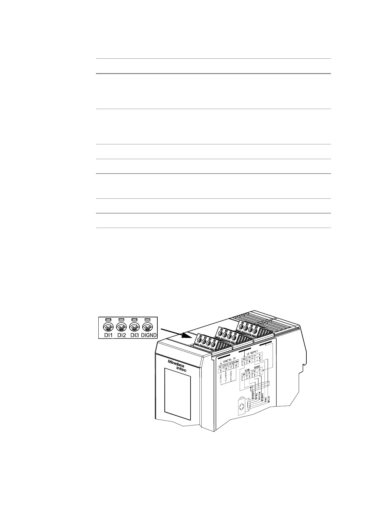
4.3.3 Digital inputs
3 passive opto-decoupled inputs are permanently built into the device. The
interface can be configured by software.
The connection diagram is located on the right side of the housing.
 Loading...