10. Safety system
MiR250 User Guide (en) 11/2020 - v.1.3 ©Copyright 2020: Mobile Industrial Robots A/S. 100
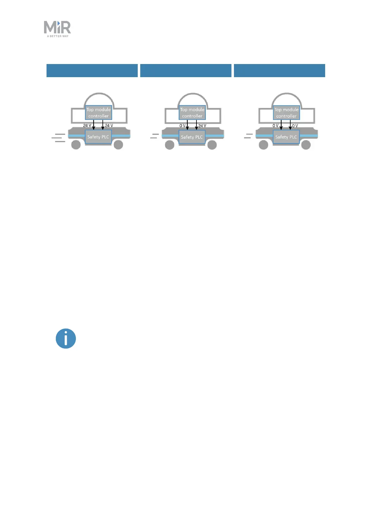
Default speed Reduced speed Reduced speed
Figure 10.11. The robot drives at its default speed only when both inputs are 24 V. If either or both pins are 0V,
the robot drives at 0.3 m/s.
Pins 4 in interfaces Aand B of the Auxiliary safety functions are used for the Reduced speed
function.
10.10 Safety stop
There are two pairs of contactors used to stop MiR250: the STO (Safe Torque Off) contactors
and the SS1 (Safe Stop 1) contactors. These are controlled by the safety PLC and are used
when the robot goes into Protective or Emergency stop. The following processes occur to
stop the robot safely:
1. The safety PLCfirst turns off the STOcontactors so power is cut from the motors.
To ensure that the STOcontactors switch states as expected, there is a
feedback circuit that connects to the safety PLC to verify that the
contractors switch to the correct state. When the robot is starting up, the
feedback circuit and STOcontactors are checked before allowing the robot
to be operated.
2. The safety PLCturns off the SS1 contactors to activate the dynamic brake function in the
motors.
3. The safety PLCmonitors data from the motor encoders to determine whether the robot
has stopped within the expected amount of time.
4. Once the robot has stopped, the mechanical brakes are engaged to keep the robot in
place, similar to the parking brake in a car.