18. Interface specifications
MiR250 User Guide (en) 11/2020 - v.1.3 ©Copyright 2020: Mobile Industrial Robots A/S. 205
18.2 Right side interfaces
This section describes the general purpose interfaces located in the right side compartment
on top of MiR250.
GPIO A and B
The GPIO interfaces have the following pins:
• Four inputs, for use with 24 V, but robust against 48 V.
• Four outputs, for use with 24 V.
The GPIO supports low current/power devices like relays, contactors, lamps, and separate
PLC units.
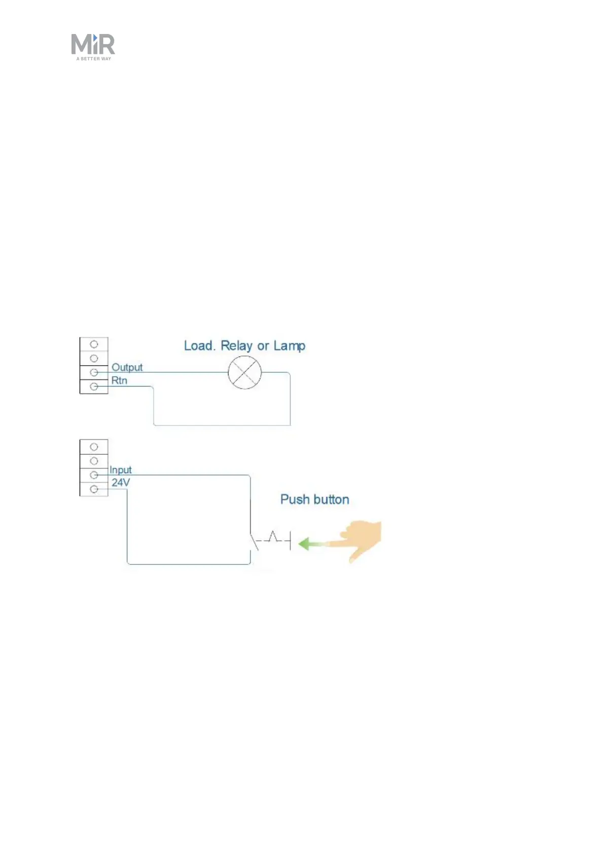
Figure 18.4. Outputs and RTNs are intended for sending signals to the top application, and inputs and 24V pins
are intended to receive signals from the top application.
To use the GPIO for a top application of your own design, ensure that the Shelf feature is
disabled by setting it to False under System >Settings >Features and that I/O modules is
enabled by setting it to True.