18. Interface specifications
MiR250 User Guide (en) 11/2020 - v.1.3 ©Copyright 2020: Mobile Industrial Robots A/S. 209
Pin no.
Signal
name
Type Description
output.
7 IN4 Input Input 4.
8 24V Output 24 V output. 2 A maximum total over all 24 V
output.
To use the GPIO functionality, it is necessary to connect the fitting FMC 1.5/ 8-ST-3.5
(1952322) connector made by Phoenix Contact.
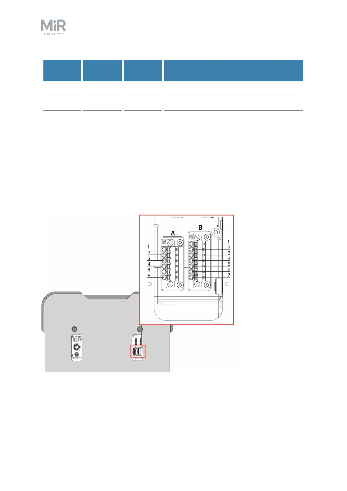
Auxiliary Safety Functions A and B
The Auxiliary safety functions interfaces are designed to support Emergency and Protective
stops and other safety functions—see Safety system on page84.
Figure 18.7. The pins of the Auxiliary safety functions interfaces.
 Loading...


