Installation
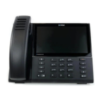
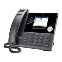
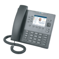
System phone
48
Socket Max. power input [mW]
Expansion key module MiVoice
M530
MiVoice 5370 300
Expansion key module MiVoice
M530
MiVoice 5380 500
Expansion key module MiVoice
M535
MiVoice 5370, MiVoice 5380
0
51
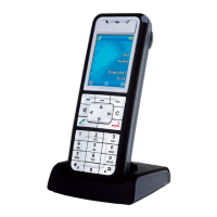
DECT radio unit without power
supply unit SB-4+
DSI-AD2 interface
1700
52
DECT radio unit without power
supply unit SB-8
2 DSI-AD2 interfaces
1550
53
DECT radio unit with power
supply unit SB-4+/SB-8
1 or 2 DSI-AD2 interfaces lt; 100
The two diagrams below show the power available on the DSI-AD2 bus in relation to the line length and the
wire diameter. The table can then be used to determine the number and type of system phones that can
be connected to the DSI-AD2 bus under the given conditions. The power available can be calculated by
measuring the loop resistance where the wire diameter is known.
Due to the different hardware versions of the radio units, the power available on the DSI-AD2 bus is not the
same in every case:
Power available case A:
• Applies to all the system phones of the MiVoice 5300 series.
• Applies to the SB-4+/SB-8 DECT radio units with hardware version "-1".
48
Assumptions:
System phones: In hands-free mode, loudspeaker on maximum volume, all LEDs lit
MiVoice 5380: Backlighting with maximum brightness
Expansion key modules: All LEDs lit
Radio units: Active call connection on all channels
51
An MiVoice M535 always requires a power supply unit
52
The value applies to radio units with hardware version “-2”. The value for hardware version “-1” is 300 mW lower.
53
The value applies to each interface and to radio units with hardware version “-2”. The value per interface for radio units with
hardware version “-1” is 150 mW lower.
Release 7.1
System Manual for Mitel SMB Controller 130
 Loading...