APPENDICES
Appendix 5 Method of replacing High Performance model QCPU with Universal model QCPU
App - 130
9
Parameters
10
Device Explanation
11
CPU Module Processing
Time
12
Procedure for Writing
Program to CPU ModuleAppendicesIndex
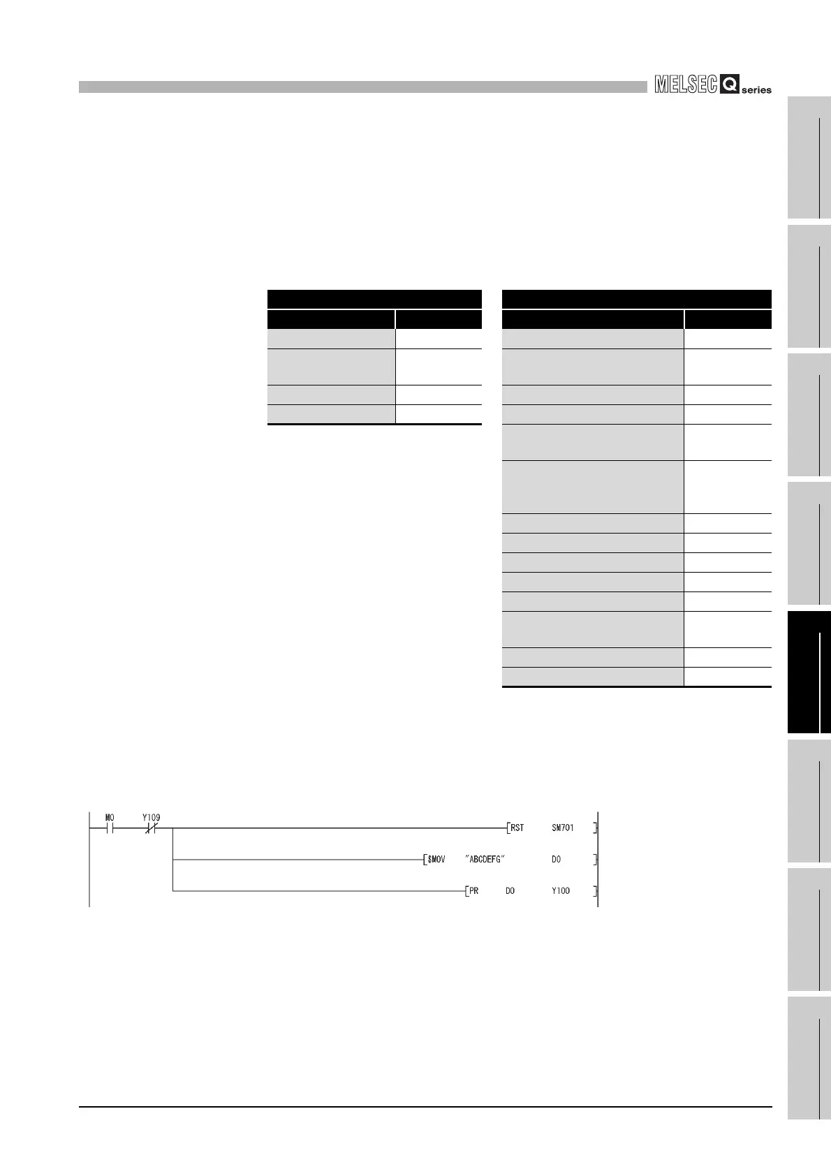
(3) Replacement example of the PR instruction
A replacement example of program using the PR instruction is shown below.
The number of output characters can be switched by the ON/OFF status of SM701.
(a) Example of device assignment
If the device numbers in the example above are used for other applications,
assign unused device numbers instead.
(b) Program before replacement
TableApp.68 Example of device assignment
Before replacement After replacement
Application Device Application Device
Output string D0 to D3 Output string D0 to D3
ASCII code output
signal
Y100 to Y107 ASCII code output signal Y100 to Y107
Strobe signal Y108 Strobe signal Y108
In-execution flag Y109 In-execution flag Y109
Output string storage address
(BIN32)
D20 to D21
Output string storage address
(BIN32)(Used for sub-routine
programs and interrupt programs)
D200 to D201
Number of output characters D202
Output module start Y number D203
Character extraction position D204
Number of extracted characters D205
String output status value D206
Result of string extraction by the
MIDR instruction
D207
String output in-execution flag M200
For index modification Z0
Figure App.6 Sample program
The number of output strings is set
to variable. (Output untill ASCII code
00
H appears.)
The strings stored in D0 or later are
output to Y100 to Y108.
 Loading...