9
DEVICE EXPLANATION
9.2 Internal User Devices
9.2.4 Latch relay (L)
9
- 12
9
Device Explanation
10
CPU Module Processing
Time
11
Procedure for Writing
Program to CPU Module
AppendicesIndex
9.2.4 Latch relay (L)
(1) Definition
Latch relays are auxiliary relays which can be latched by the programmable
controller's internal latch (memory backup).
Latch relay operation results (ON/OFF information) are saved even in the following
cases:
• When the PLC is powered OFF and then ON
• When the CPU module is reset
The latch is backed up by the CPU module battery.
(2) Latch relay clear
Turn OFF the latch relays by latch clear operation.
However, the latch relay set to "Latch (2) first/last" in the device setting of the PLC
parameter dialog box cannot be turned OFF if latch clear is performed by the RESET/
L.CLR switch
Note9.2
.Note2
(3) Number of used N/O and N/C contacts
There are no restrictions on the number of contacts (N/O contacts, N/C contacts)
used in the program, provided the program capacity is not exceeded.
Note2
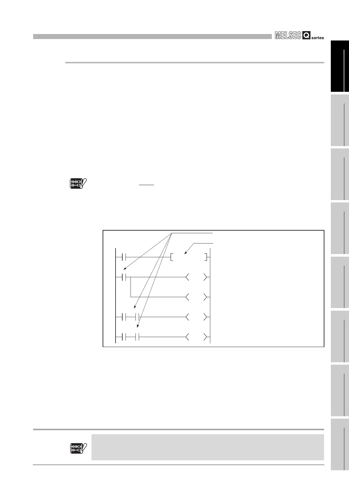
Diagram 9.10 Latch Relay
Basic
Note9.2
In the case of the Basic model QCPU, latch clear cannot be performedd by switch operation.
Basic
Note9.2
X0
L0
T0
Y20
X1 L0
L100
X2 L0
L2047
SET L0
K20
The latch relay (L0) ON can only be used for
internal CPU module processing, and cannot be
output externally.
No restrictions on the quantity used.
L0 switches ON at X0 OFF to ON.
L0 ON/OFF information is output from the output
module to an external destination.
 Loading...

