11
PROCEDURE FOR WRITING PROGRAM TO CPU
MODULE
11.2 High Performance Model QCPU, Process CPU, Redundant CPU
11.2.5 Boot run procedure
11
- 16
9
Device Explanation
10
CPU Module Processing
Time
11
Procedure for Writing
Program to CPU Module
AppendicesIndex
11.2.5 Boot run procedure
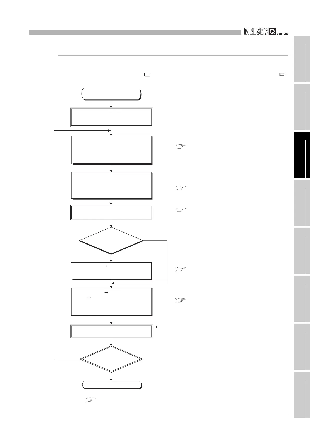
This section explains a boot run procedure.
In the following procedure, indicates the operation on the GX Developer side, and
indicates that on the Basic model QCPU side.
1 : Refer to the following manual for the procedure when the Redundant CPU is used.
QnPRHCPU User's Manual (Redundant System)
Diagram 11.7 Boot run flowchart
Start (Continued from
Section 11.2.3,11.2.4)
When the RUN/STOPT switch is in the
RUN position, set the switch to the
STOP position.
In the boot file setting of the PLC
parameter dialog box, set the parameter,
program, device initial value and device
comment file names to be read from the
standard ROM or memory card.
In the program setting of the PLC
parameter dialog box, set the program
names to be executed and their execution
conditions (they must also be set if one
program is to be executed).
Set the parameter-valid drive of the DIP
switches (SW2, SW3).
Power the PLC OFF and then ON, or
reset the CPU module.
Is the BOOT
LED on?
End
YES
NO
YES
NO
Choose [Online] [Format PLC memory]
on GX Developer, and format the
memory.
Choose [Online] [Write to PLC (Flash
ROM)] [Write to PLC (Flash ROM)] on
GX Developer, and write data to the
memory set as the "transfer source" in
the boot file setting.
Part names and settings of QCPU User's Manual
(Hardware Design, Maintenance and Inspection)
Section 5.2.8
GX Developer Operating Manual
Section 3.3.6
Section 5.2.5
Use the standard
RAM or memory card
(except Flash card)?
1
 Loading...

