9
DEVICE EXPLANATION
9.3 Internal System Devices
9.3.1 Function devices (FX, FY, FD)
9
- 42
9
Device Explanation
10
CPU Module Processing
Time
11
Procedure for Writing
Program to CPU Module
AppendicesIndex
9.3 Internal System Devices
Internal system devices are used for system operations.
The allocations and sizes of internal system devices are fixed, and cannot be changed by
the user.
9.3.1 Function devices (FX, FY, FD)
(1) Definition
Function devices are used in subroutine programs with arguments.
The function devices write/read data between a subroutine call source with argument
and a subroutine program with argument.
(2) Applications of function devices
Because the function devices used for each subroutine program CALL source can be
set, the same subroutine program can be used without regard to other subroutine
CALL sources.
(3) Types of function devices
There are 3 function device types: function input devices (FX), function output devices
(FY), and function register devices (FD).
(a) Function input devices (FX)
• These devices are used to designate inputs of ON/OFF data to a subroutine
program.
• In the subroutine program, these devices are used for reading and
processing bit data designated by subroutine with argument CALL
instruction.
• All the CPU module bit data designation devices can be used.
(b) Function output devices (FY)
• These devices are used to designate outputs of subroutine program operation
results (ON/OFF data) to the subroutine program CALL source.
• The operation results are stored at the device designated by using subroutine
programs with arguments.
• All bit data designation devices except CPU module inputs (X, DX) can be used.
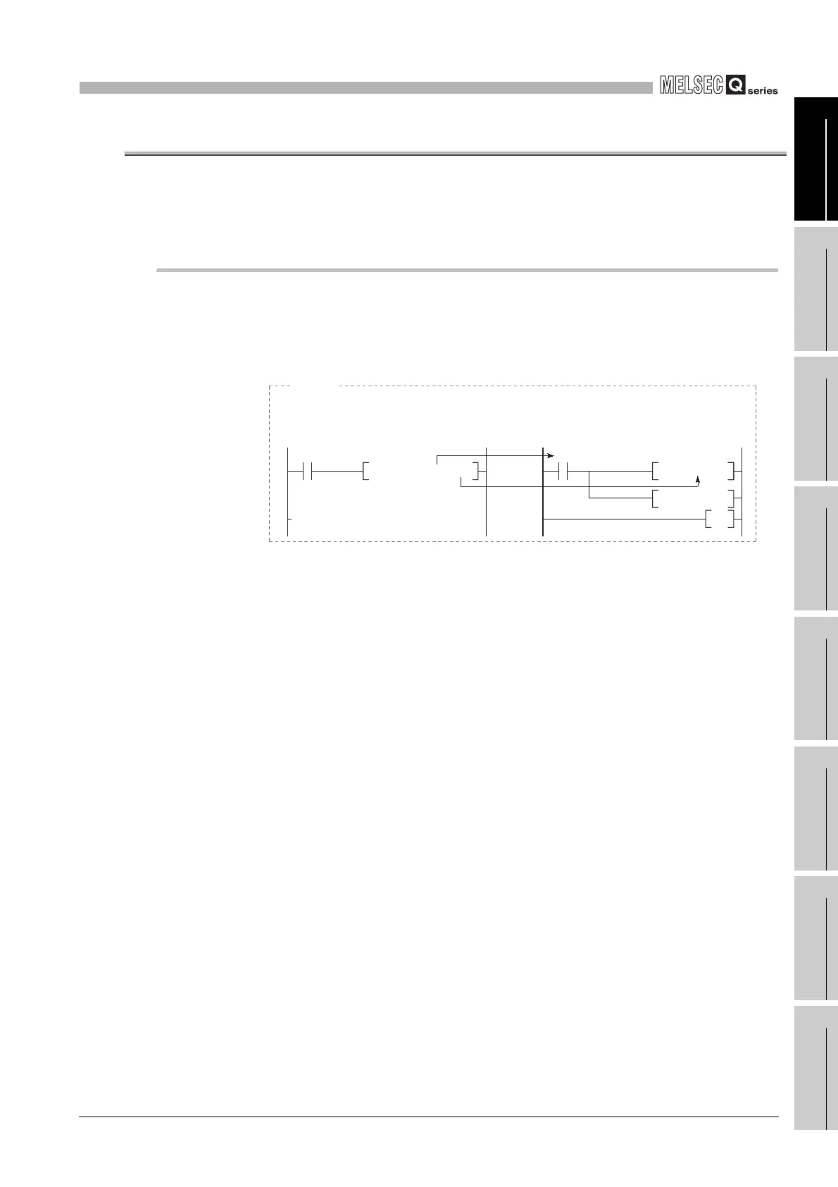
Diagram 9.42 Application example of function devices
M0 D0P0 X0
CALL
FD1 R0
FY1
MOV
SET
RET
X0 FX0
P0
If FX0 and FD1 are used at the subroutine program, and if M0 and D0 are designated by the
subroutine CALL instruction, the M0 ON/OFF data is transferred to FX0, and the D0 data is
transferred to FD1.
[Subroutine program CALL source]
[Subroutine program]
Example
 Loading...

