9
DEVICE EXPLANATION
9
- 43
9.3 Internal System Devices
9.3.1 Function devices (FX, FY, FD)
(c) Function registers (FD)
• Function registers are used to perform write/read of data between the sub-
routine call source and the subroutine program.
• The function register I/O condition is automatically determined by the High
Performance model QCPU. If the subroutine program data is the source data,
the data is designated as subroutine input data.
If the subroutine program data is the destination data, the data is designated
as subroutine output data.
• 1 function register occupies a maximum of 4 words.
The number of words used depends on an instruction in a subroutine
program.
A one-word instruction requires 1 word.
A two-words instruction requires 2 words.
The destination of 32-bit multiplication/division operation requires 4 words.
CPU module word data devices can be used.
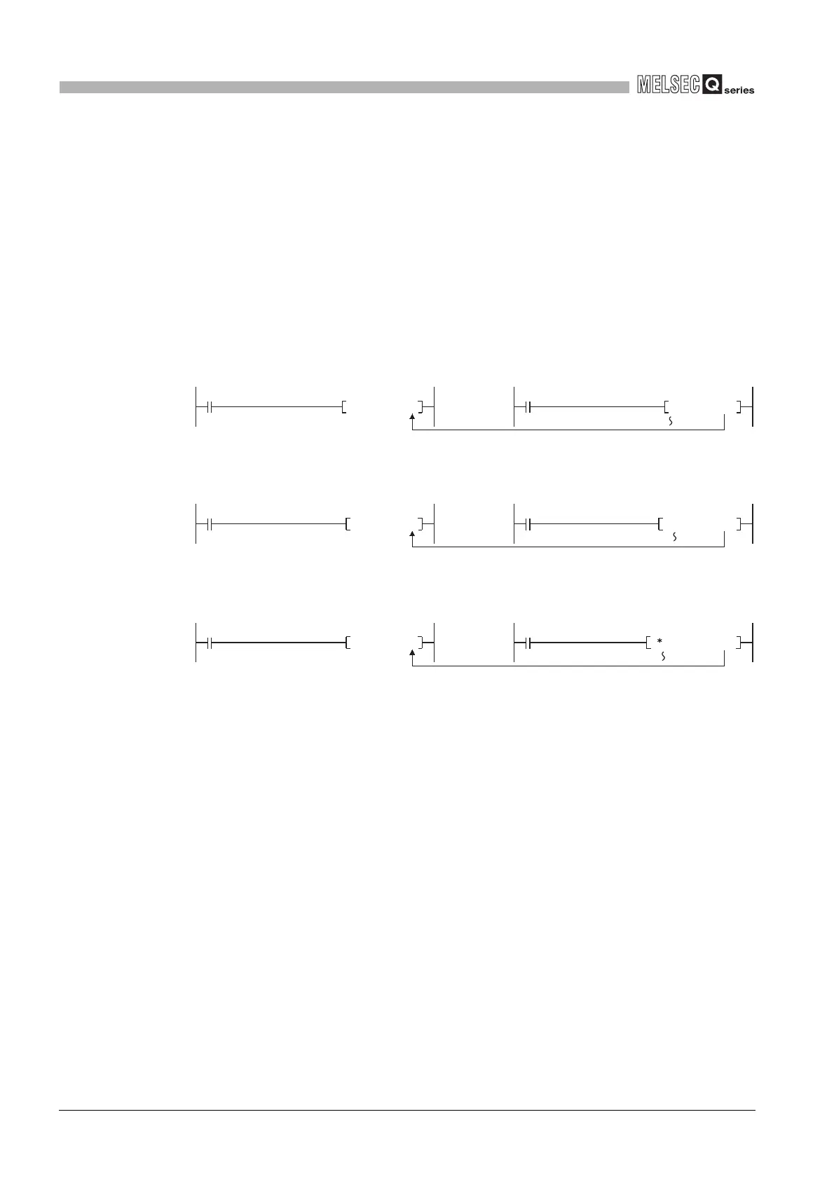
Diagram 9.43 When 1 word is occupied by 1 function register
Diagram 9.44 When 2 words are occupied by 1 function register
Diagram 9.45 When 4 words are occupied by 1 function register
P0
The data is stored in one point (D0).
CALLP P0 D0
MOV R0 FD0
CALLP P0 D0 DMOV R0 FD0
P0
The data is stored in two points (D0 and D1).
CALLP P0 D0
D R0 R10 FD0
P0
The data is stored in four points (D0 to 3).
 Loading...

