9
DEVICE EXPLANATION
9.3 Internal System Devices
9.3.3 Special register (SD)
9
- 46
9
Device Explanation
10
CPU Module Processing
Time
11
Procedure for Writing
Program to CPU Module
AppendicesIndex
9.3.3 Special register (SD)
(1) Definition
A special register is used to store CPU module status data (diagnosis and system
information).
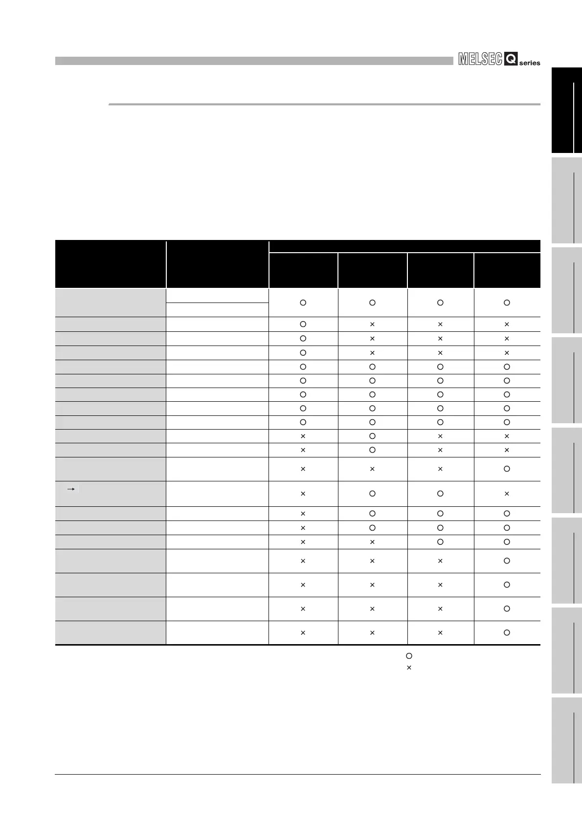
(2) Special register classifications
Special registers are classified according to their applications, as shown in Table9.9.
: Usable special relay is included
: Usable special relay is not included
* 1 : In the Basic model QCPU, SD0 to 99 will be the area for error diagnostics.
The serial communication function, fuse blown module and check of I/O modules data are stored
into SD100 to 199.
* 2 : In the High Performance model QCPU, Process CPU or Redundant CPU, SD0 to 199 will the area
for error diagnostics.
The fuse blown module and check of I/O modules data are stored into SD1300 to 1499.
* 3 : Usable only when "Use the special relays/special registers SM1000/SD1000 and later" is selected
in the PLC system setting of the PLC parameter dialog box.
Table9.9 Special register classification list
Classification Special register
CPU module
Basic model
QCPU
High
Performance
model QCPU
Process CPU Redundant CPU
Diagnostics information
SD0 to 99
*1
SD0 to 199
*2
Serial communication function
SD100 to 129
*1
Fuse blown module
SD130 to 149
*1
Check of I/O modules
SD150 to 199
*1
System information SD200 to 399
System clock/system counter SD400 to 499
Scan information SD500 to 599
Memory card SD600 to 699
Instruction related SD700 to 799
debugging SD800 to 899
Latch area SD900 to 929
Redundant function (power
failure backup information)
SD952
A Q/QnA conversion
compatibility
SD1000 to 1299
Fuse blown module
SD1300 to 1399
*2
Check of I/O modules
SD1400 to 1499
*2
Process control instruction SD1500 to 1509
Redundant system (host
system CPU information)
SD1510 to 1599
Redundant system (other
system CPU information)
SD1600 to 1699
Redundant system (tracking
information)
SD1700 to 1779
Redundant power supply
module information
SD1780 to 1799
 Loading...

