4
- 20
4.6 Concept of I/O Number Assignment
4.6.1 I/O numbers of base unit
4
I/O NUMBER ASSIGNMENT
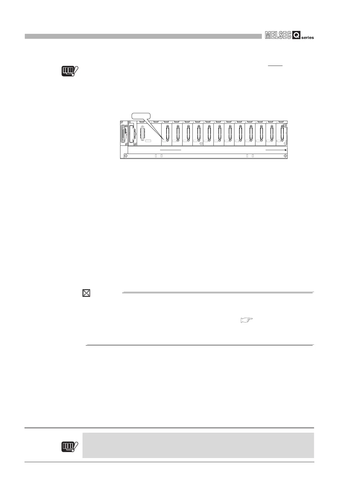
(3) Order of I/O number assignment for extension base units
Note4.5
Note5
The I/O numbers for extension base units continue from the last number of the I/O
number of the main base unit.
The I/O numbers are assigned to the extension base units from left (I/O 0) to right
consecutively as shown in Diagram 4.18, in the order in which the setting connectors
of the extension base unit are set.
(4) I/O numbers of each slot
Each slot of base units occupies the points of I/O numbers of the mounted I/O
modules or intelligent function modules .
When 32-point input module is mounted on the right of CPU module, X0 to X1F are
assigned as I/O numbers.
(5) I/O numbers of empty slots
If the base unit has empty slots mounted with no I/O modules or no intelligent function
modules (special function modules) are mounted, the points designated at the "I/O
assigment" tab screen in the "(PLC) Parameter" dialog box are assigned to the empty
slots. (Default value is 16 points.)
POINT
When the assignment of base units is conducted in Auto mode, the number of
empty extension stages is not assured even if the extension stage is skipped at
the stage number setting connector of the base unit.( Section 4.3(2)(a))
To reserve empty extension stages for future expansion, use the PLC parameter
to set the base unit.
Note5
Diagram 4.18 I/O number assignment order
Note4.5
Redundant
For the Redundant CPU, extension base units are not available.
Redundant
Note4.5
I/O11I/O10I/O9I/O8I/O7I/O6I/O5I/O4I/O3I/O2I/O1I/O0
POWER
5V
56
OUTIN
I/O 0
Serial numbers inorder from left to right
 Loading...

