1. CONFIGURATION
1.3.5 Remote box
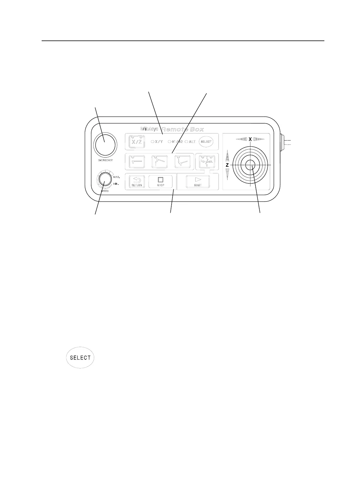
Fig.1-11 shows the external view of the remote box.
2.
Axis selection keys 4. Stylus keys
6.
Emergency stop switch
5. S
eed ad
ustment knob 1. Joystick
3.Measurement related ke
s
Fig. 1-11
1. Joystick
The X axis or Z axis moves in the direction towards which the lever is moved and
the detector feeds. The moving speed varies depending on the inclination angle
of the joystick lever.
Keeping the joystick lever at an angle (45°) allows for the simultaneous movement
of the two axes.
2. Axis selection keys
Enable or disable the function of each axis with the joystick. Disable the axis key
that will not be operated to prevent malfunction due to accidental contact.
SELECT key
This key is used to select an axis that can be driven by the joystick.
Each time the key is pressed, the selected axis changes in the following order:
X/Z → X/Y→θ1/θ2 → ALT.
The axis for which the corresponding LED is lit can be moved by manipulating the
joystick. After power-on, the X/Z key is enabled.
X/Y, θ1/θ2, and ALT are enabled only when the optional Y axis, the optional
θ1-axis table or θ-axis unit, and the optional auto-leveling table, respectively, are
connected.
No. 99MBB187A
1-15
Artisan Technology Group - Quality Instrumentation ... Guaranteed | (888) 88-SOURCE | www.artisantg.com
 Loading...