64BTop Panel Components 6BChapter Three: Overview
40
• If either switch is in the network (PGM) position at power-up, the data rate or address is
read from the nonvolatile memory. Any changes to the values must be made over the
network. Any changes in the rotary switch positions after power-up are ignored.
• If the rotary switch is not in the network (PGM) position at power-up, the data rate or
address is read directly from the switches. Network changes will be denied and the
Attribute_Not_Settable General Error Code will be returned to the Set_Attribute_Single
service request.
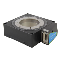
Data Rate Switch
The 4-position rotary
switch (Figure 6) is used to select the DeviceNet data rates of 125, 250, and
500 Kb. The switch positions are num
bered in a clockwise direction, to correspond to the
increasing data rate values.
Figure 6: Data Rate Rotary Switch
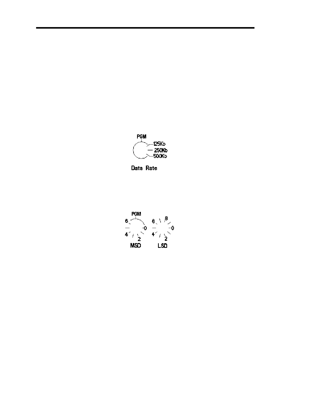
Node Address Switches
Two 10-position rotary
switches (Figure 7) are used to set the node address.
Figure 7: Node Address Rotary Switches
Use the switch on the left to set the m
ost significant digit (MSD)— the factor of ten (10, 20,
30...60). Use the switch on the right to set the least significant digit (LSD)—the increments of
one (1, 2, 3...9). The switch positions are numbered in a clockwise direction to correspond to the
increasing address values.
Artisan Technology Group - Quality Instrumentation ... Guaranteed | (888) 88-SOURCE | www.artisantg.com
 Loading...