6BChapter Three: Overview 67BLabels
43
Labels
Note
The drawings in Figures 8 and 9 are not drawn to scale.
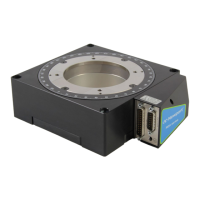
Band Label
The band label, which is wrapped around the transducer body, lists the pinouts for the unit’s
5-pin micro-style digital communications connector (Table 9, page 28) and the 9-pin Type
DE-9S analog interface connector (Table 10, page 29).
Figure 8: Band Label
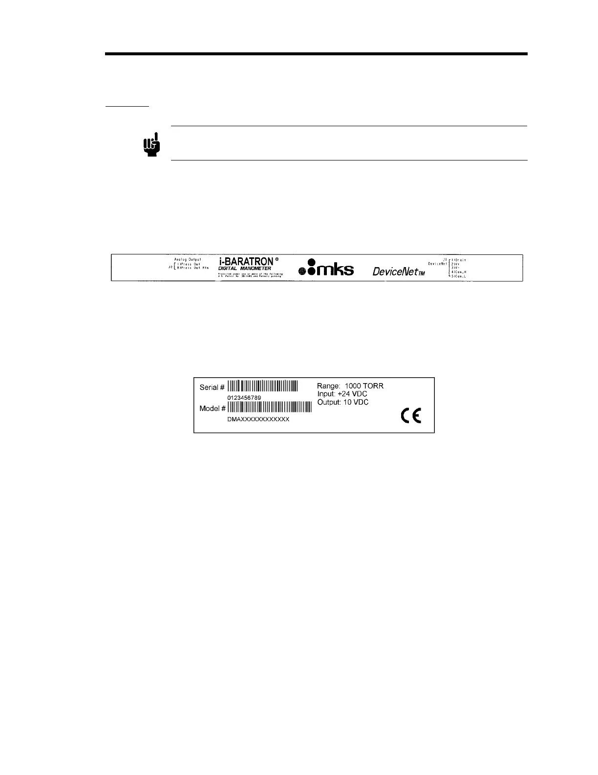
Serial Number Label
The serial number label, located on the lower enclosure, lists the unit’s serial number, product
m
odel code, full scale range, input voltage, output voltage, and firmware revision level. The label
also displays the CE mark signifying compliance with the European CE regulations.
Figure 9: Serial Number Label
The options for your transducer are identified in the m
odel code when you order the unit. Refer to
Appendix B: Model Code Explanation, page 91, for more information.
Artisan Technology Group - Quality Instrumentation ... Guaranteed | (888) 88-SOURCE | www.artisantg.com
 Loading...