50/126
D14D Camera Manual: Mounting
www.mobotix.com • sales@mobotix.com
First Installation Steps2.3
Mounting Lens Units2.3.1
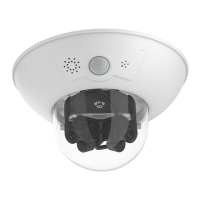
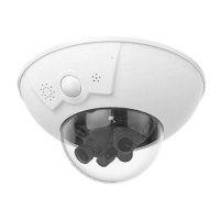
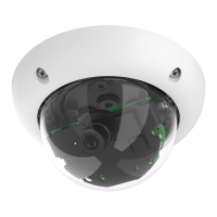
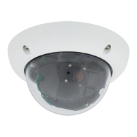
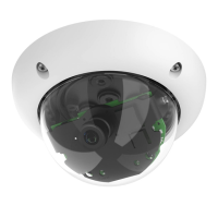
The standard models in the MOBOTIX D14D family are supplied with a pre-installed dome.
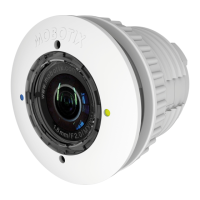
Lens units (lens mount, image sensor and lens) are usually delivered separately. Lens units
are installed as described below if this is the case.
The sensor cables to connect the image sensors are marked with R (right) and L (left).
Depending on the type of sensor used, the sensors (mounted on the lens units) are marked
either by the RGB icon (color) or the SW icon (BW, black & white).
The following combinations of sensor cables (L, R) and sensors (color, black & white) are
possible:
Image Sensor Combination Sensor cable L Sensor cable R
Color/Color
l l
l
Note
Make sure that you only use the combinations of image sensors and sensor cables
listed in the table!
When setting up the camera, the installed combination of image sensors has to be
set in the camera’s browser user interface. You can do so either automatically by
running the (
) or manually by
opening the
Admin Menu > Image Sensor Configuration dialog box.