Dansensor A/S COPYRIGHT © P/N 330654-E 01/2018
Lippke 4000/4500 EN User Guide 25
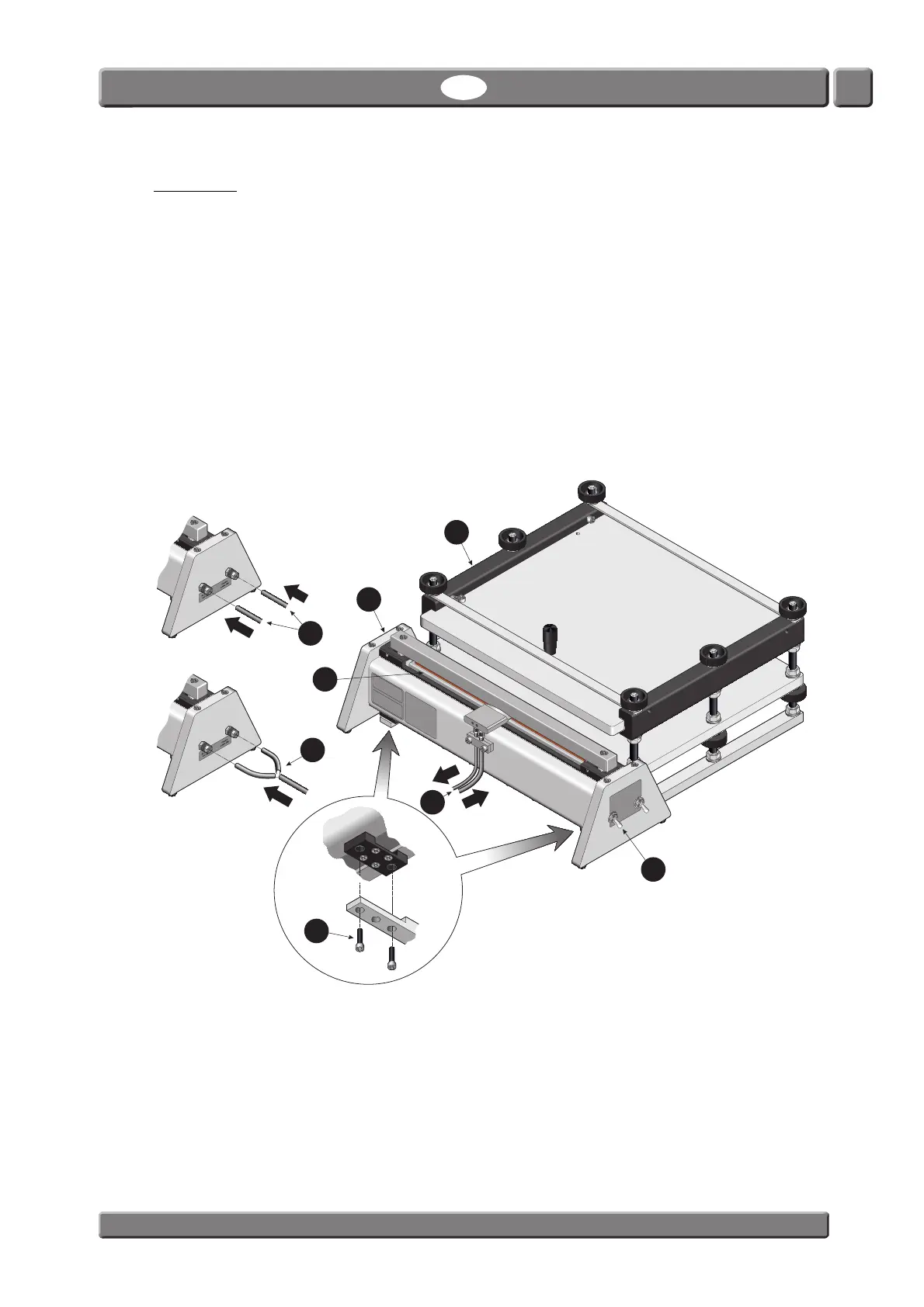
Setting Up
1. If the PPC 300 II is to be used together with the fixture for package restraining the two units
must be assembled using the screws
.
2. Connect the unit’s air supply (Feed) and pressure measurement (Sense) hoses
to the Lippke
4000/4500.
3. Connect air supply hoses
for the clamp control:
- If you want the Lippke 4000/4500 to control the lower clamp bar
, connect an external air
supply hose to “Air Supply 4-6 Bar” inlet and a hose from “Clamp” outlet on the Lippke 4000/4500
to the “Control Lower Bar” inlet on the PPC 300 II.
- If you want to control the lower clamp bar
yourself by means of the switch , connect external
air supply hose(s) (4-6 Bar) to each of the “Air Supply 4-6 Bar” and “Control Lower Bar” inlets on
the PPC 300 II.
This type of equipment complies
with the applicable ANSI/UL
Standard for Safety, including
Electrical Fire and Shock Hazards
This type of equipment has been
tested against EN 983 and
EN ISO 12100-2.
A copy of the certicate is
available at the Manufacturer.
Lower Bar
Up / Auto
Down
PP
C
30
0II
Lippke
a
M
O
C
ON c
o
m
p
an
y
Down
Upper Bar
Up
1
6
7
5
5
3
2
Sense
Feed
Clamp
4-6 Bar
4-6 Bar
4