Chapter 4 Installation Gen 3 Site Controller System Manual
Intercabling Connections
4-50 68P80801E30-A 5/1/2002
Punch Block Signal Pair Definitions
Table 4-24 lists the system alarm/control signal connections available on
punch block 1. Table 4-25 lists the user alarm/control signal connections
available on punch block 2.
Note: Although punch block 2 is typically defined as the “user” alarm/
control interface, punch block 2 also contains system connections
reserved for RFCs 4 through 8. These connections are identified
accordingly.
The punch block signal pairs consist of a signal and its respective return
connection. In all cases, the lower-number of the pair is the signal function
(“hot” connection) and the higher-number is its return.
In certain cases, jumpering from punch block 1 to punch block 2, or between
the right and left sides of punch block 2 is required. In Tables 4-24 and 4-25,
these are identified as entries containing four punch block numbers per
alarm function. In these cases, a jumper is required from the pin indicated in
the particular row to the pin indicated in the immediately adjacent column.
Figure 4-21 shows examples of punch block-to-punch block jumpering.
EAS/EAS2 Modular Alarm Connections
Table 4-26 lists the alarm connections at modular connectors RF#1 through
RF#3 on the EAS/EAS2 rear panel.
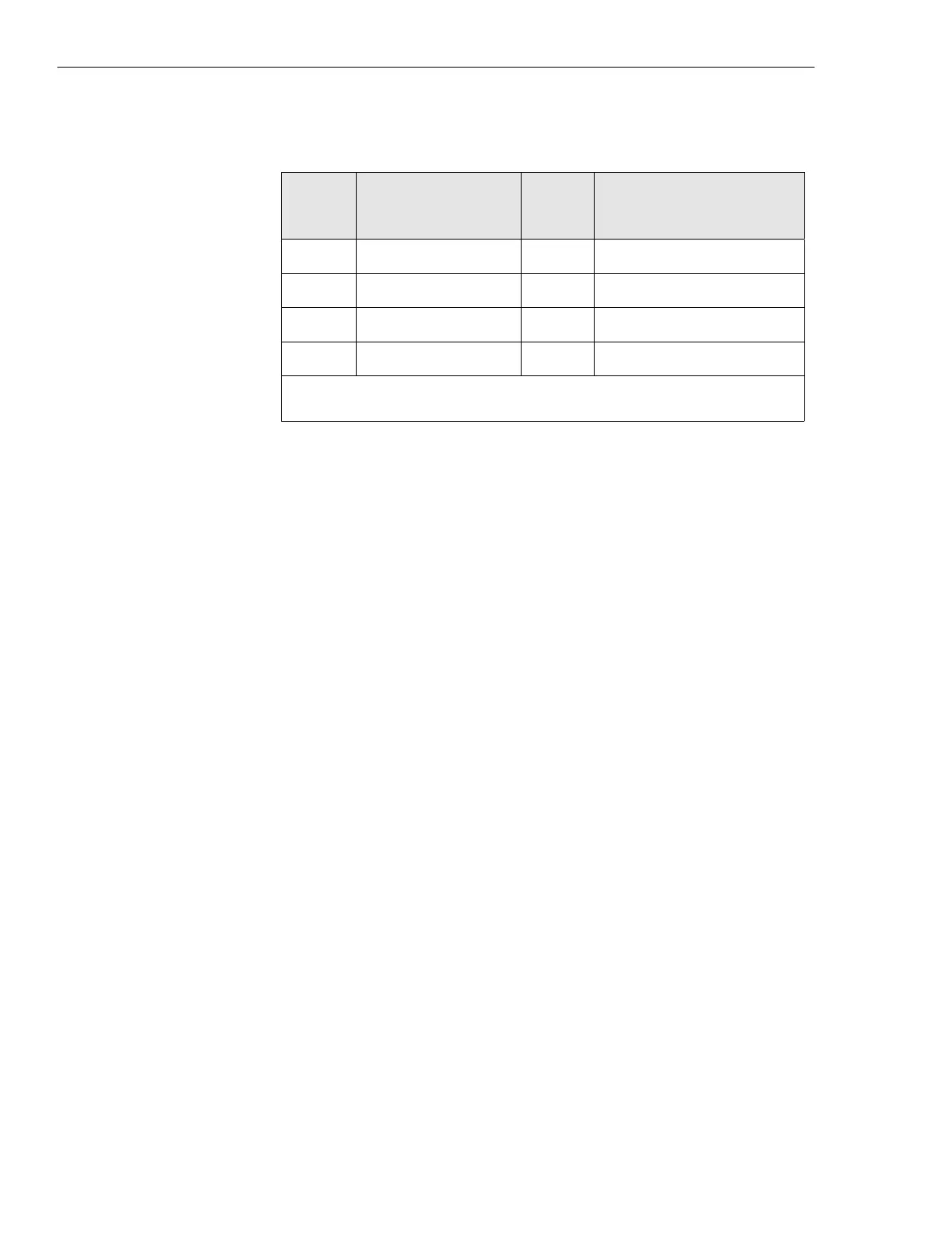
253* System/Alarm Control 26, 2, 1 reserved for system use
254* System/Alarm Control 28, 4, 3 reserved for system use
255* User/Alarm Control 26, 2, 1 customer defined output
256* User/Alarm Control 28, 4, 3 customer defined output
* These alarms are outputs controlled by the EAS/EAS2 and/or OMC.
Table 4-23 Punch block pinouts — continued
Alarm
code
EAS/EAS2
connector
Punch
block
pairs
EAS/EAS2 standard
alarm connection
 Loading...


