6-30 Computer Group Literature Center Web Site
Jumpers, Connectors, and LEDs
6
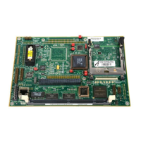
LEDs (DS1–DS8) on board the MBX. The following table describes the
function of the on-board LEDs.
Note This table shows the recommended configuration. Statuses of
DS4, DS5, and DS6 may vary because their functions are defined
by software and controlled via control register #2. The current
release of EPPCBug does not support these status indicators. If
you are using EPPCBug, DS4, DS5, and DS6 will always be on
(lit).
Table 6-19. On-board LED Status Indicators
LED Status
at Reset
Function
DS3 (green) On +3.3Vdc OK; lights when +3.3Vdc power is
available on the MBX board.
DS1 (green) On +5Vdc OK; lights when +5Vdc power is available on
the MBX board.
DS2 (green) On +12Vdc OK; lights when +12Vdc power is available
on the MBX board.
DS4
(orange)
Off Board failure; lights when a fault is present on the
MBX board. (See note.)
DS5
(yellow)
Off Battery status; lights when the on-board or external
battery is low. (See note.)
DS6
(yellow)
Off Flash programming status; lights when the Flash is
being reprogrammed. (See note.)
DS7 (green) Off CPU activity; lights when the MPC8xx processor bus
is active. Should extinguish when board is reset.
DS8 (green) Off PCI activity; lights when the PCI bus is active. Valid
only on standard configurations of the MBX board;
should remain off on entry-level configurations.

 Loading...