PC/104 (ISA) Expansion Connector J21/J22
http://www.motorola.com/computer/literature 6-25
6
PC/104 (ISA) Expansion Connector J21/J22
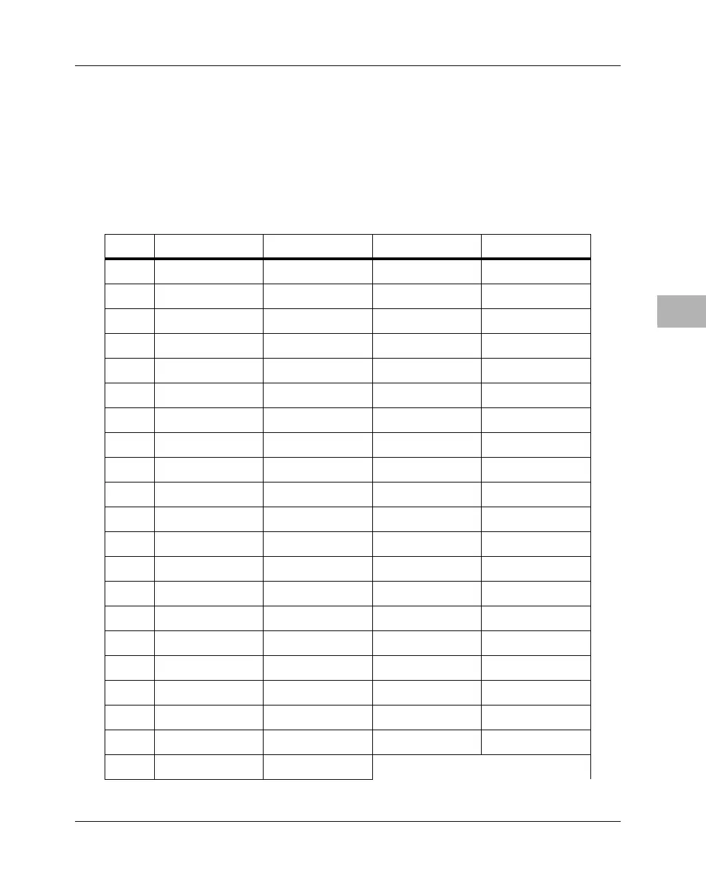
Two connectors, a 2 × 20-pin (J21) and a 2 × 32-pin (J22) socket, make up
the PC/104 ISA bus expansion connector. The pin assignments for the
PC/104 connector are listed in the following table.
Table 6-15. PC/104 Expansion Connector Pin Assignments
Pin # Row A Row B Row C Row D
1 IOCHK# GND GND GND
2 SD7 RSTISA SBHE# MEMCS16#
3 SD6 +5V LA23 IOCS16#
4 SD5 INT9 LA22 INT10
5SD4 −5V LA21 INT11
6 SD3 DRQ2 LA20 INT12
7SD2 −12V LA19 INT15
8 SD1 ENDXFR# LA18 INT14
9 SD0 +12V LA17 DACK0#
10 IOCHRDY Key MEMR# DRQ0
11 AEN SMEMW# MEMW# DACK5#
12 SA19 SMEMR# SD8 DRQ5
13 SA18 IOW# SD9 DACK6#
14 SA17 IOR# SD10 DRQ6
15 SA16 DACK3# SD11 DACK7#
16 SA15 DRQ3 SD12 DRQ7
17 SA14 DACK1# SD13 +5V
18 SA13 DRQ1 SD14 MASTER#
19 SA12 REFRESH# SD15 GND
20 SA11 ISACLK Key GND
21 SA10 INT7

 Loading...


