Utility Connector J19
http://www.motorola.com/computer/literature 6-29
6
Utility Connector J19
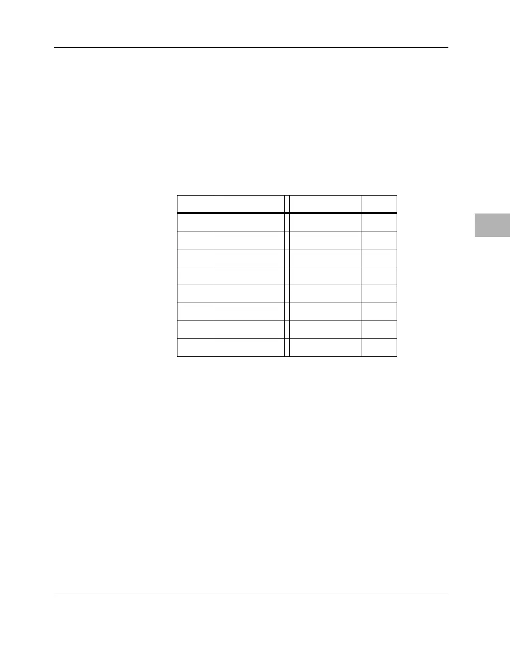
A 16-pin dual-row header known as “Utility Connector #2” supplies the
interface between the MBX series embedded controller and external
devices such as the keyboard and mouse. This utility connector is only
available on standard configurations. The pin assignments for this
connector are listed in the following table.
MBX LED Status Indicators
In addition to the six status signals (five for Ethernet activity and one for a
hard disk drive) available via utility connector #1, there are eight status
Table 6-18. Utility Connector #2 (J19) Pin Assignments
Pin # Signal Signal Pin #
1KDATA KCLK 2
3+5V fused MCLK 4
5 MDATA GND 6
7 IR_TXD GND 8
9 IR_RXD +5V 10
11 COM2_RXD COM2_RTS# 12
13 COM2_TXD COM2_CTS# 14
15 Reserved Reserved 16

 Loading...


