Test Port Header J23
http://www.motorola.com/computer/literature 6-13
6
Test Port Header J23
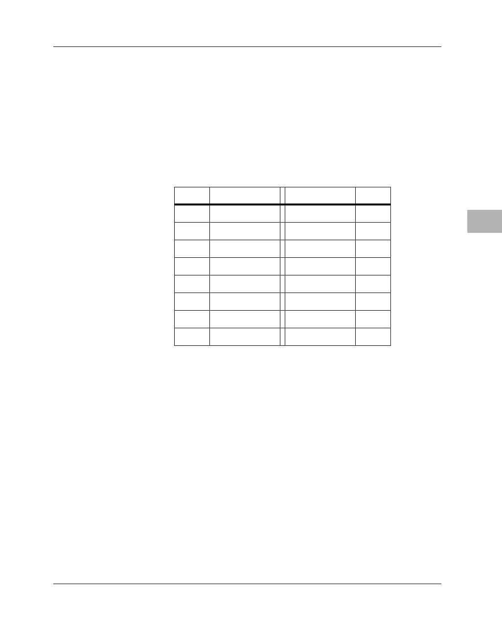
A 16-pin header (J23 on MBX series boards) provides access to an IEEE
1149 test port. The pin assignments are listed in the following table.
Note To enable this port, you must configure jumper header J5 (see J5
Test/Debug Port Selection on page 6-7).
Debug Port Header J24
A 10-pin header (J24 on MBX series boards) provides access to Debug
port signals. The pin assignments are listed in the following table.
Table 6-4. Test Port Header Pin Assignments
Pin # Signal Signal Pin #
1TDO 2
3TDI TRST# 4
5 +3.3V 6
7TCK 8
9 TMS 10
11 SRESET# 12
13 HRESET# Key 14
15 GND 16

 Loading...


