6-28 Computer Group Literature Center Web Site
Jumpers, Connectors, and LEDs
6
Floppy Disk Connector J17
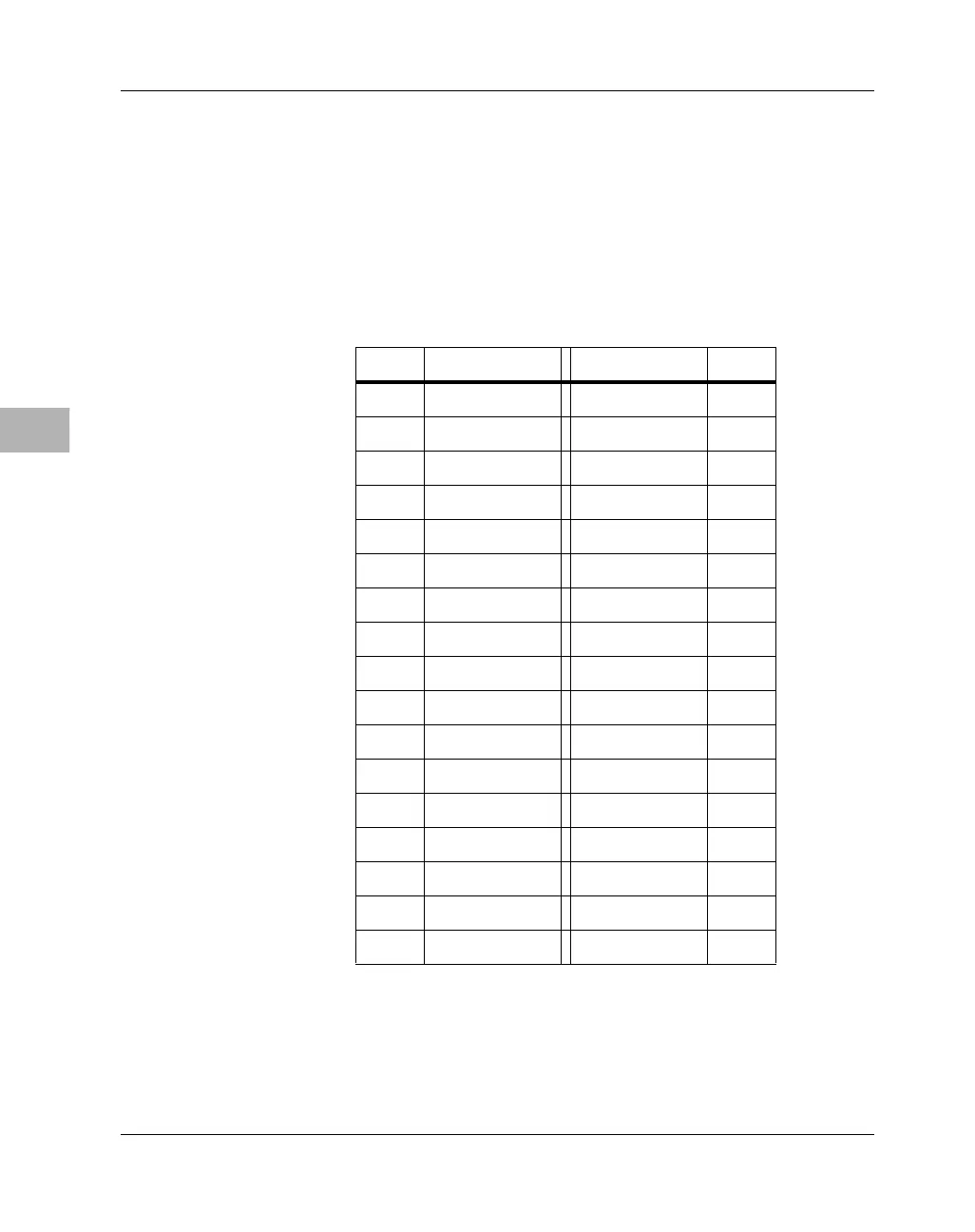
A 34-pin dual-row header supplies the interface between the MBX series
embedded controller and external floppy disk drives. The pin assignments
for the floppy disk drive connector are listed in the following table.
Table 6-17. Floppy Disk Drive Connector Pin
Assignments
Pin # Signal Signal Pin #
1 GND DRVDEN0# 2
3GND Reserved 4
5 GND DRVDEN1# 6
7 GND INDEX# 8
9GND MTR0# 10
11 GND DRV1# 12
13 GND DRV0# 14
15 GND MTR1# 16
17 GND DIR# 18
19 GND STEP# 20
21 GND WDATA# 22
23 GND WGATE# 24
25 GND TRK0# 26
27 GND WRPRO# 28
29 GND RDATA# 30
31 GND HDSEL# 32
33 GND DSKCHG# 34

 Loading...


