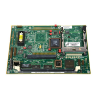
Utility Connector J16
http://www.motorola.com/computer/literature 6-21
6
Utility Connector J16
A 20-pin dual-row header known as “Utility Connector #1” supplies the
interface between the MBX series embedded controller and external
devices such as status LEDs, Reset and Abort switches, and power sources.
The pin assignments for this utility connector are listed in the following
table.
33 BRCOMM# BDIP# A24 A25
34 BGCOMM# BURST# A26 A27
35 RD/WR# FRAME_L A28 A29
36 CLK LOAD_L A30 A31
Table 6-11. 821/COMM Expansion Connector Pin Assignments
Pin Row A Row B Row C Row D
Table 6-12. Utility Connector #1 (J16) Pin Assignments
Pin # Signal Signal Pin #
1 +3.3V −12V 2
3+5V −5V 4
5 ResetSwitch# Battery Plus 6
7 ETHTX LED# Battery Minus 8
9 ETHRX LED# Power Fail Sense# 10
11 ETHCOL LED# Stop Interrupt# 12
13 ETHTPI LED# GND 14
15 ETHTPP LED# IDE LED# 16
17 Battery Low# Flash Programming# 18
19 MBX Bus Activity# PCI Bus Activity# 20

 Loading...