6-26 Computer Group Literature Center Web Site
Jumpers, Connectors, and LEDs
6
Note Rows C and D are not required on 8-bit modules.
EIDE Connector J14
A 44-pin dual-row header supplies a connection point for an EIDE
(Enhanced IDE) hard disk subsystem. The EIDE header permits a direct
ribbon cable connection between the MBX series embedded controller and
user-installed 2.5-inch hard disk drives. The pin assignments for the EIDE
connector are listed in the following table.
22 SA9 INT6
23 SA8 INT5
24 SA7 INT4
25 SA6 INT3
26 SA5 DACK2#
27 SA4 TC
28 SA3 BALE
29 SA2 +5V
30 SA1 OSC
31 SA0 GND
32 GND GND
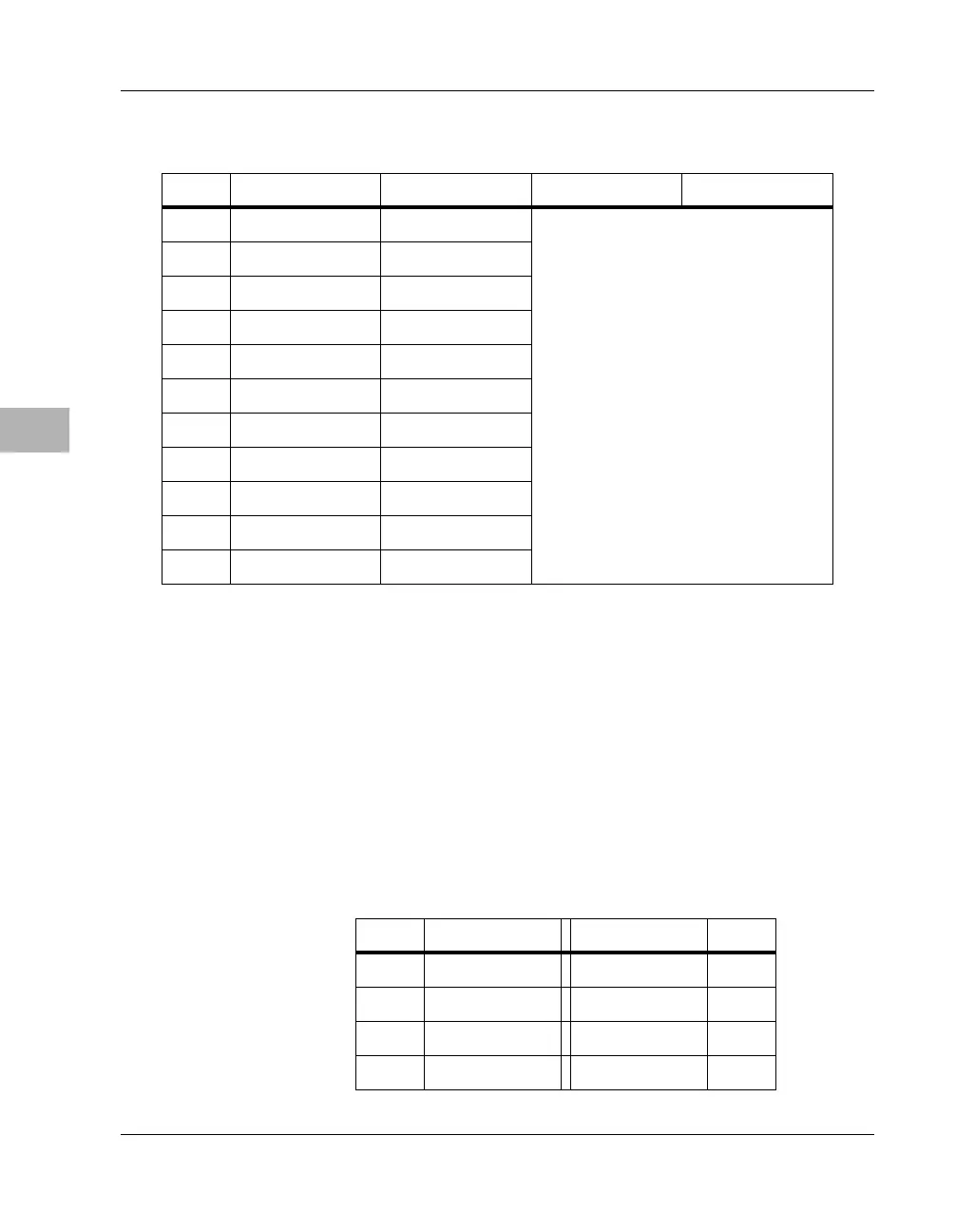
Table 6-15. PC/104 Expansion Connector Pin Assignments (continued)
Pin # Row A Row B Row C Row D
Table 6-16. EIDE Connector Pin Assignments
Pin # Signal Signal Pin #
1 RST# GND 2
3D7 D8 4
5D6 D9 6
7D5 D10 8

 Loading...


