J7 IDE Interface Configuration
http://www.motorola.com/computer/literature 6-9
6
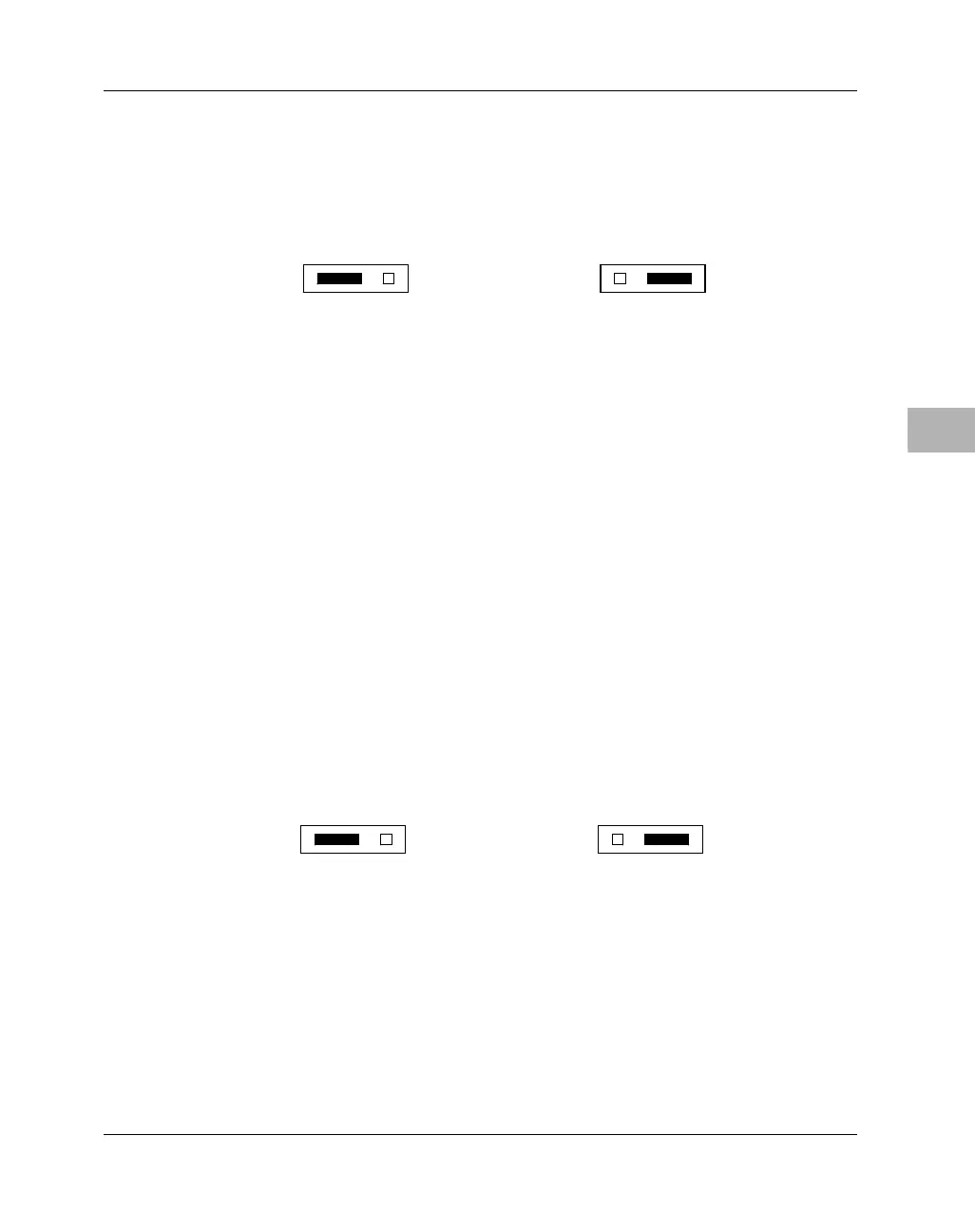
Placing a jumper on J6 pins 1 and 2 configures the MBX for external
arbitration. Placing a jumper on J6 pins 2 and 3 (the default) configures the
MBX for internal arbitration.
J7 IDE Interface Configuration
IDE I/O controllers can be categorized as either “legacy” or “native”
devices. “Legacy” devices use a hard-wired addressing scheme with fixed
interrupt requests. The more recent “native” (also known as Bus Master
IDE) devices use controller registers that are relocatable in I/O space, with
interrupt requests mapped to the appropriate registers.
Use J7 to configure the IDE interface on MBX series boards as necessary
for the devices you have installed.
Placing a jumper on J7 pins 1 and 2 configures the IDE interface for native
addressing mode. Placing a jumper on J7 pins 2 and 3 (the default)
configures the IDE interface for legacy addressing mode.
For additional details on programming IDE devices, refer to the MBX
Series Embedded Controller Version B Programmer’s Reference Guide
(listed in Appendix B, Related Documentation).
Internal Arbitration
(factory configuration)
2150 9802
J6
1 2 3
External Arbitration
J6
1 2 3
Legacy IDE Mode
(factory configuration)
2151 9802
J7
1 2 3
Native IDE Mode
J7
1 2 3

 Loading...


